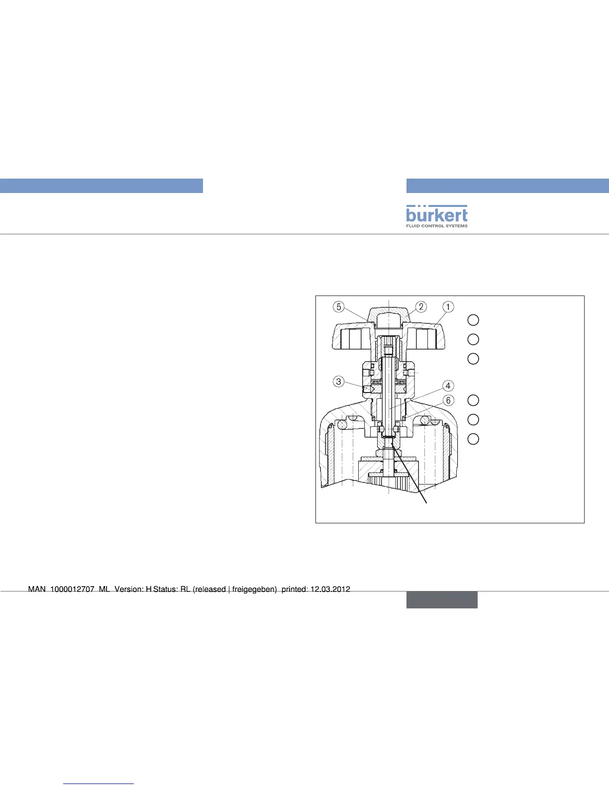
EasyManuals Logo

Burkert 2000 Assembly Instructions

Burkert 2000
88 pages
To Next Page IconTo Next Page
To Previous Page IconTo Previous Page
Page #21 background imageLoading...
Page #21 background image
21
Option: Hand wheel


the stop is not required.
Screw guide spindle
with spindle extension into actuator
(WAF36).
Screw lower nut
onto guide spindle ②.
Position bridge
on spindle extension and fix with cap screw
(cap screw M16 x 45, Allan key WAF12). Secure cap screw
with Loctite 274.
Screw upper nut
onto guide spindle ②.
Set max. and min. stroke by means of upper and lower nuts
and lock in each case with second nut ③.
Test valve for function and leaktightness
Place tube onto stroke limitation and screw cover by hand
onto guide spindle ②.


Loctite 274

1
Hand wheel
2
Transparent cap
3
Setscrew
3 x without locking paint
2 x with locking paint
4
Pull rod
5
O-ring
6
O-ring
Actuators D-50 to H-125 with hand wheelFig. 9:
english



Table of Contents

Other manuals for Burkert 2000

Questions and Answers:

Question and Answer IconNeed help?

Do you have a question about the Burkert 2000 and is the answer not in the manual?

Burkert 2000 Specifications

General IconGeneral
Model2000
ManufacturerBurkert
Ambient Temperature-10 to +60 °C
Protection ClassIP65
Operating Temperature-10 to + °C
Seal MaterialFKM
Operating Pressure0- bar
Fluid Temperature-10 to + °C

Related product manuals