25
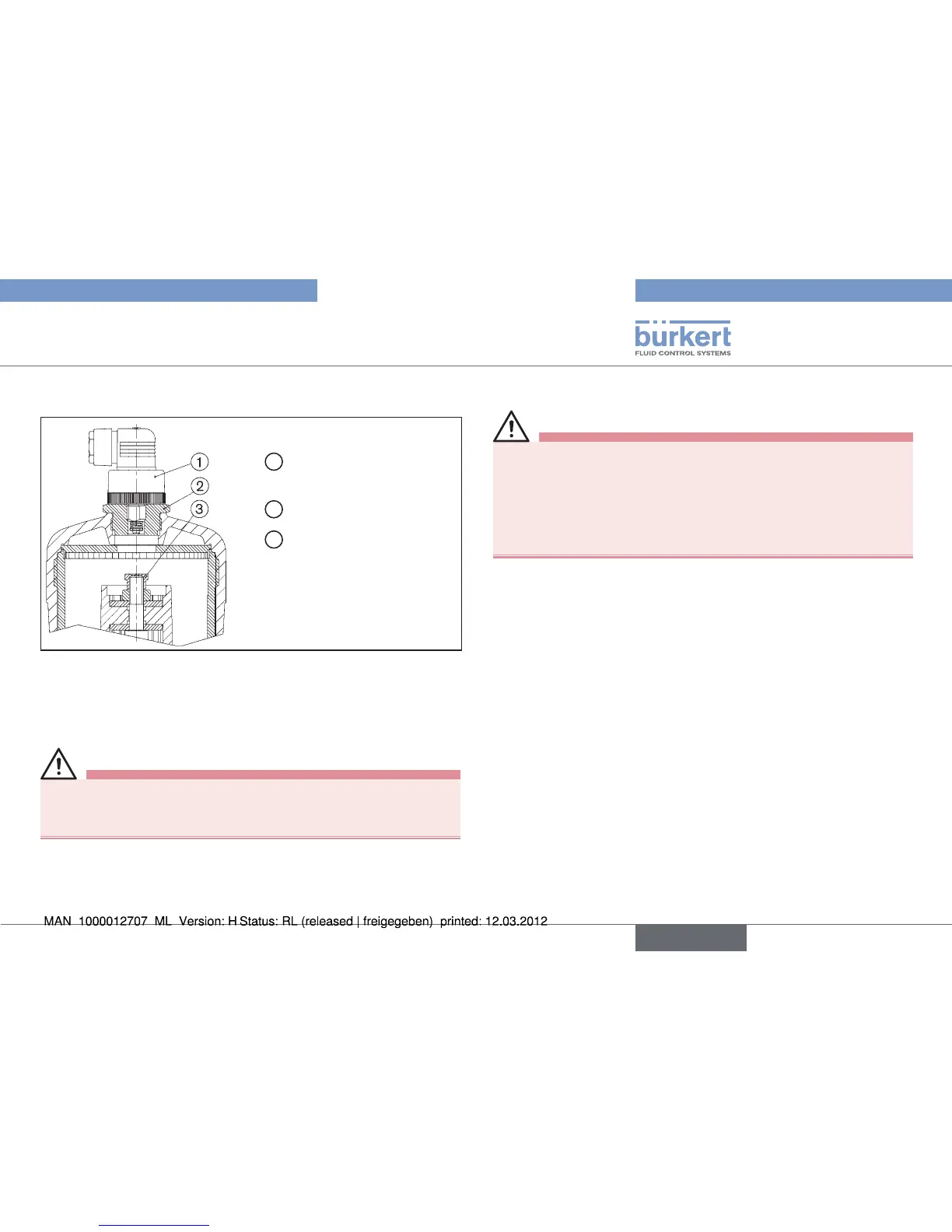
Option: Electrical position repeater
1
Electrical position repeater
with appliance socket
2
Adapter
3
Threaded sleeve
(only for Types 2030,2031)
Fig. 13: Actuators G-100, H-125 with electrical position repeater
Interrupt the control air and fluid infeed before modifying the •
devices and reduce the pressure in the fluid system.
Interrupt supply of medium
→
Empty valve housing. →
Bring actuator into the upper piston position. →
The visibility hood must not be pressurized during attachment.
Therefore pressurize only the lower piston area via the lower •
control air connector using compressed air.
Unscrew transparent cap from actuator cover.
→
Screw off position indicator with Allan key (WAF8). →
→ Screw threaded sleeve ③ onto actuator
spindle (WAF14).
Then interrupt supply of control air.
→
Screw adapter → ② instead of transparent cap onto actuator
(see “Fig. 13: Actuators G-100, H-125 with electrical position
repeater”).
Screw electrical position repeater
→ ① into adapter ②
(see “Fig. 13: Actuators G-100, H-125 with electrical position
repeater”).
english