16
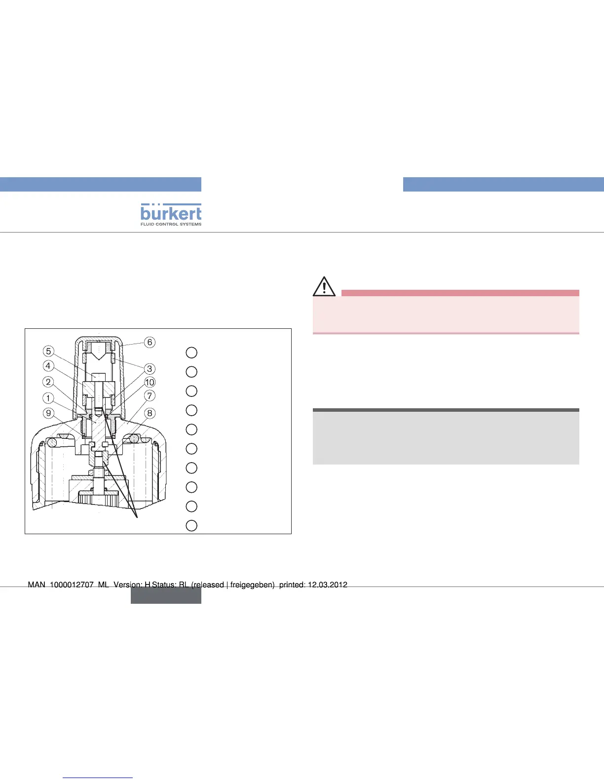
Option: Min. /max. stroke limitation
Loctite 274
1
Spindle
2
Guide spindle
3
Nut, slotted
4
Bridge (actuator)
5
Cap screw
6
Transparent cap
7
Cover
8
Coupling
9
O-ring
10
O-ring
Actuators D-50, E-63, Fig. 6:
min. / max. stroke limitation with optical position display
Interrupt the control air and fluid infeed before modifying the •
devices and reduce the pressure in the fluid system.
Interrupt supplies of control air and medium
→ .
Empty valve housing
→ .
Unscrew transparent cap
→ from actuator cover.
Screw out position indicator with Allan key (
→ WAF5 or WAF8).
Only the special wrench provided by Bürkert for the purpose •
must be used to screw down the actuator cover.
(see chapter on assembly accessories).•
Screw off actuator cover with special wrench, counterbracing at
→
the sleeve.
Screw coupling → ⑧ onto valve spindle and secure with Loctite
274.
Hook spindle
→ ① in coupling ⑧.
Grease spindle
→ ①.
english