19
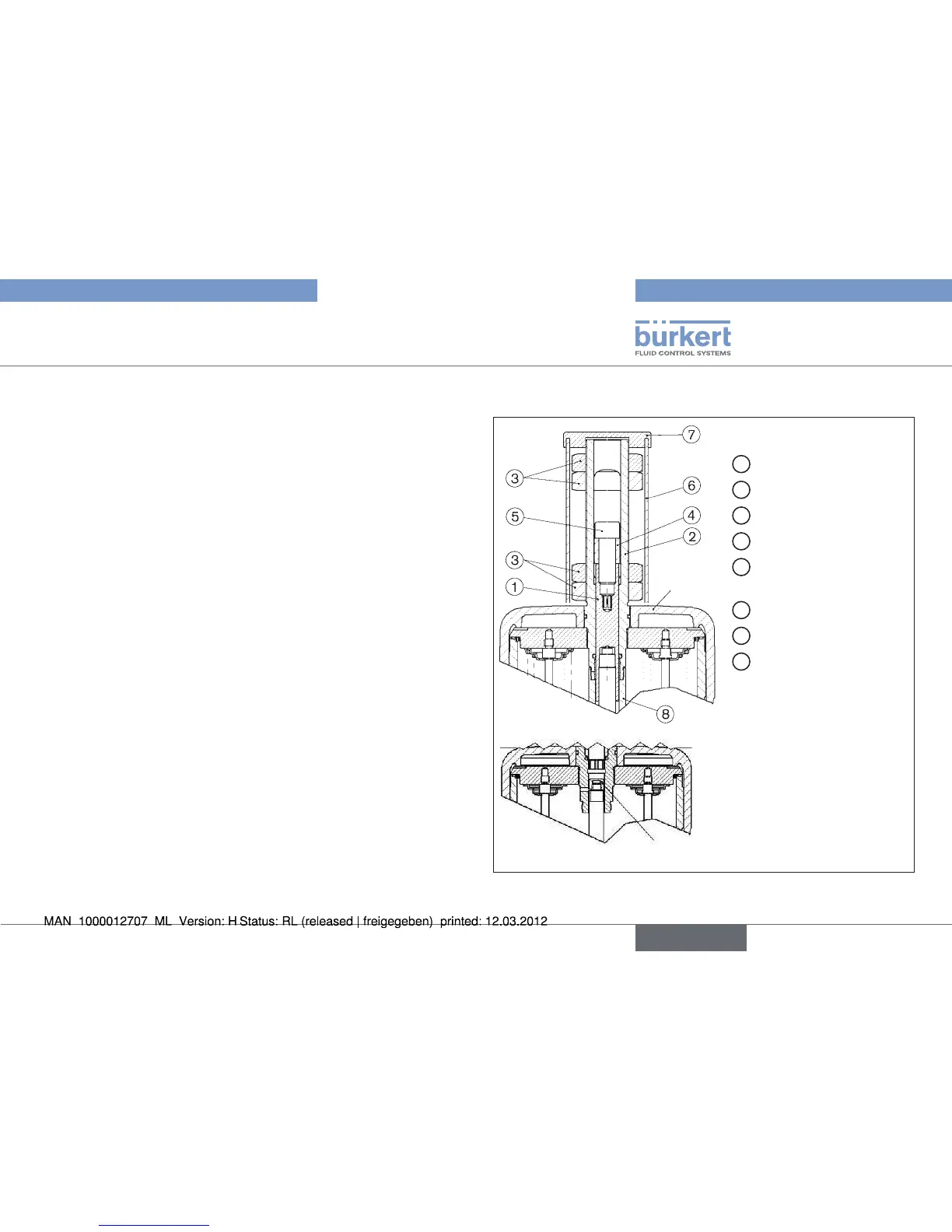
Option: Min. /max. stroke limitation
Screw coupling → ⑧ onto valve spindle and secure with Loctite
274.
Hook spindle
→ ① in coupling ⑧.
Grease spindle
→ ①.
Grease o-ring
→ ⑨ and insert into guide spindle ②.
Insert guide spindle
→ ② into actuator cover.
Insert disk into the actuator cover, attach to the guide spindle
→ ②
with the nut ⑩ and secure with Loctite 274.
To do this, use the width flat on the guide spindle
→ ② (WAF24).
• Max. tightening torquet: 20 Nm
Screw actuator cover onto valve
→
• Max. tightening torque: G-100 = 45 Nm
H-125 = 60 Nm.
Screw lower nut
→ ③ onto guide spindle ②.
Position bridge
→ ④ on spindle ① and fix with cap screw ⑤ (Allan
key WAF5 or WAF8). Secure cap screw ⑤ with Loctite 274.
Screw upper nut
→ ③ onto guide spindle ②.
Set max. and min. stroke by means of upper and lower nuts
→ ③.
Test valve for function and leaktightness.
→
Screw on tube → ⑥ with cover ⑦ by hand.
Actuator
Spindle cap
1
Spindle extension
2
Guide spindle
3
Nut M40 x 2
4
Bridge
5
Cap screw
M16 x 45
6
Tube
7
Cover
8
Stop
(for Type 2012 SFA only)
Fig. 8: Actuators K-175, L-225
min. / max. stroke limitation with optical position display
english