14
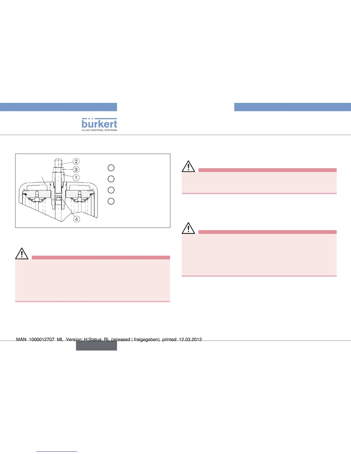
Option: Maximum stroke limitation
Actuator
1
Threaded nipple
2
Setscrew M16 x 80
3
Nut M16
4
Spindle cap
Actuators K-175, L-225, Fig. 5:
maximum stroke limitation without position repeater
The actuators contain pre-tensioned springs that may derail or slip
on improper opening.
Actuators K-175 and L-225 shall only be opened in our factory •
or by the responsible distributor.
Interrupt the control air and fluid infeed before modifying the •
devices and reduce the pressure in the fluid system.
Interrupt supply of medium.
→
Empty valve housing. →
Bring actuator into the upper piston position. →
The visibility hood must not be pressurized during attachment.
Therefore pressurize only the lower piston area via the lower •
control air connector using compressed air.
Unscrew transparent cap from actuator cover.
→
Screw out position indicator (yellow screw cap) by hand. →
Screw threaded sleeve or spindle cap → ④ instead of the position
indicator onto the end of the spindle (WAF14).
Interrupt supply of control air.
→
english