11
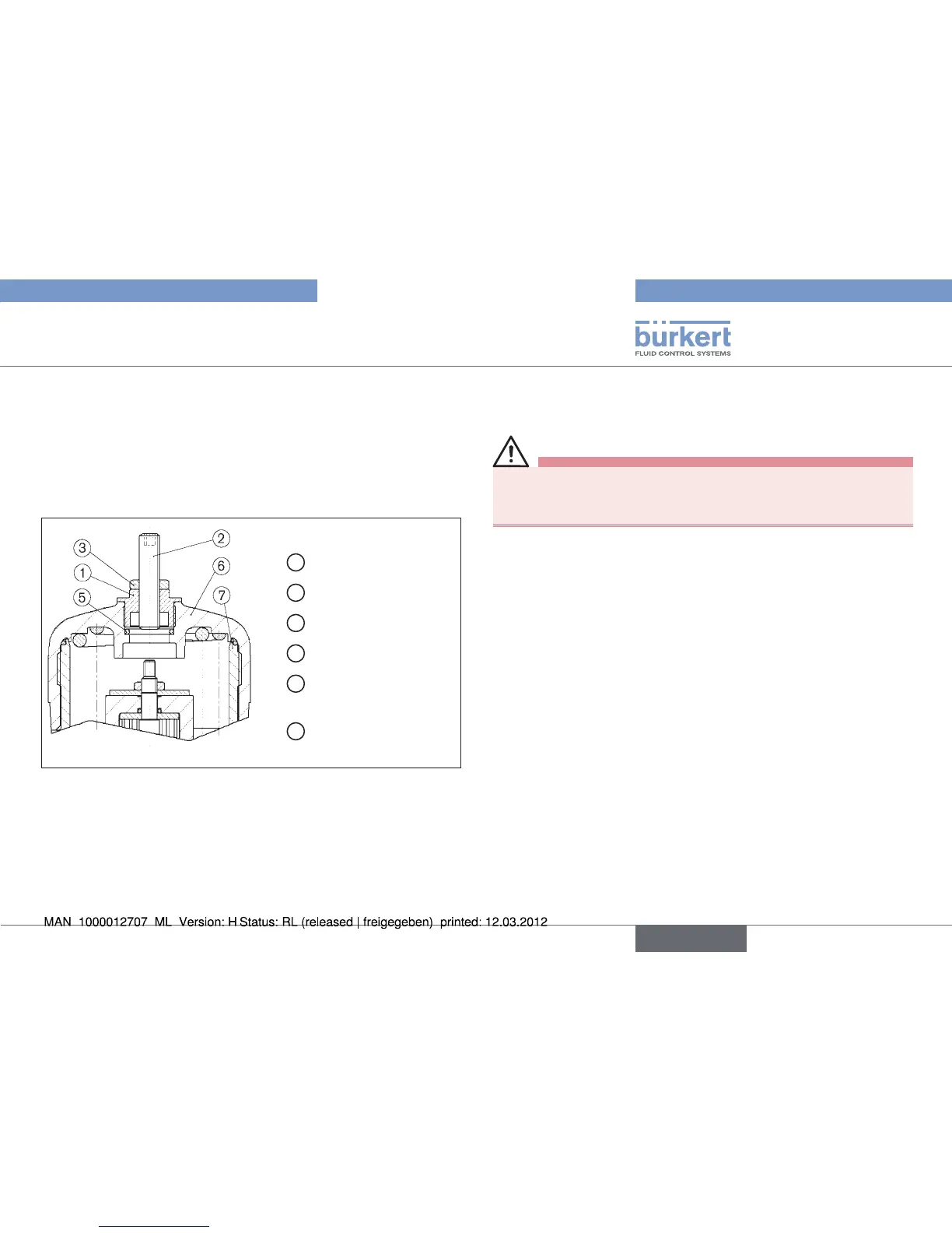
Option: Maximum stroke limitation
1
Threaded nipple
2
Setscrew M12 x 1.5
3
Nut M12 x 1.5
5
O-ring (actuator)
6
Acutator cover
(actuator))
7
Sleeve (actuator)
Actuators D-50, E-63 and F-80, Fig. 3:
maximum stroke limitation without position repeater
Interrupt the control air and fluid infeed before modifying the •
devices and reduce the pressure in the fluid system.
Interrupt supplies of control air and medium
→ .
Empty valve housing
→ .
Unscrew transparent cap
→ from actuator cover ⑥.
Screw out position indicator with Allan key (
→ WAF5).
Screw threaded nipple → ① into actuator cover ⑥
• Use flats on tube for wrench (WAF17)
• Max. tightening torque: 15 Nm
Set max. stroke by adjusting the setscrew
→ ②.
Secure setscrew
→ ② with nut ③.
Test valve for function and leaktightness.
→
english

 Loading...