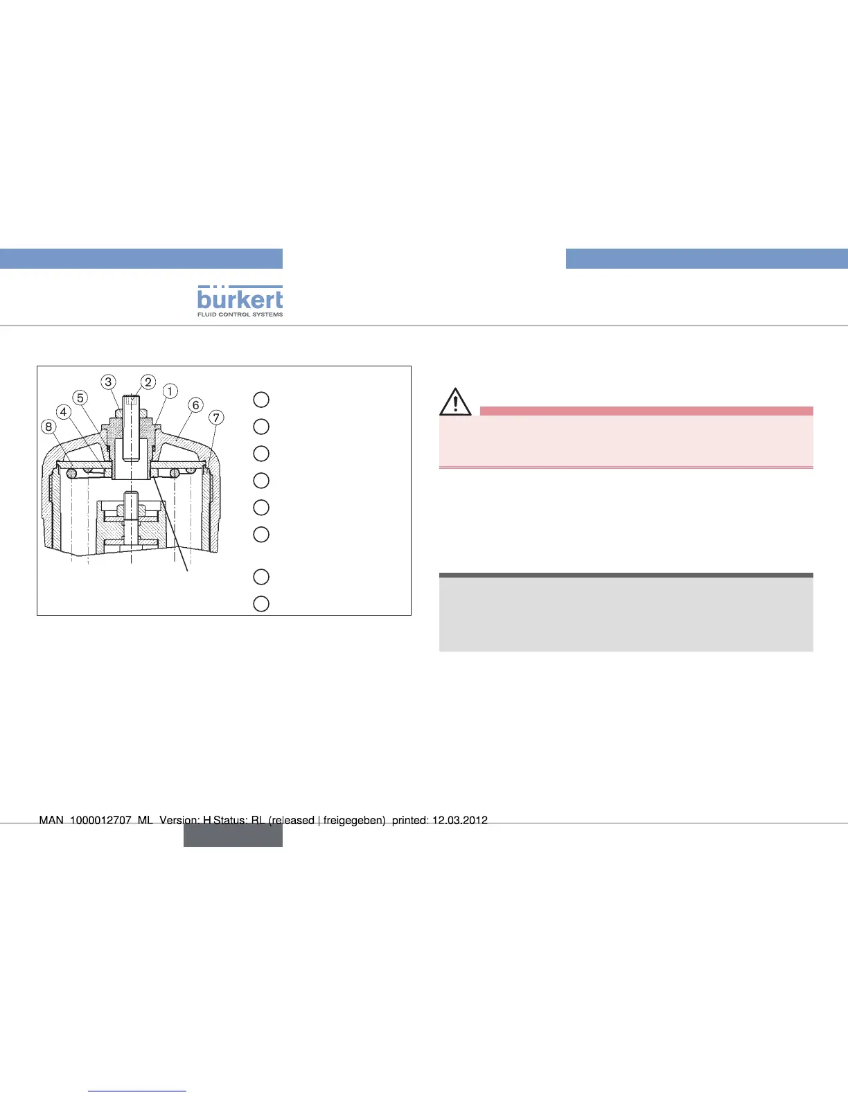
12
Option: Maximum stroke limitation
Loctite 274
1
Threaded nipple
2
Setscrew M12 x 1.5
3
Nut M12 x 1.5
4
Nut
5
O-ring (actuator)
6
Acutator cover
(actuator)
7
Sleeve (actuator)
8
Disk (actuator)
Actuators G-100, H-125, Fig. 4:
maximum stroke limitation without position repeater
Interrupt the control air and fluid infeed before modifying the •
devices and reduce the pressure in the fluid system.
Interrupt supplies of control air and medium
→ .
Empty valve housing
→ .
Unscrew transparent cap
→ from actuator cover ⑥.
Screw out position indicator with Allan key (
→ WAF8).
Only the special wrench provided by Bürkert for the purpose •
must be used to screw down the actuator cover.
(see chapter on assembly accessories).•
Screw off actuator cover
→ ⑥ with special wrench, counterbracing
at the sleeve.
english