24
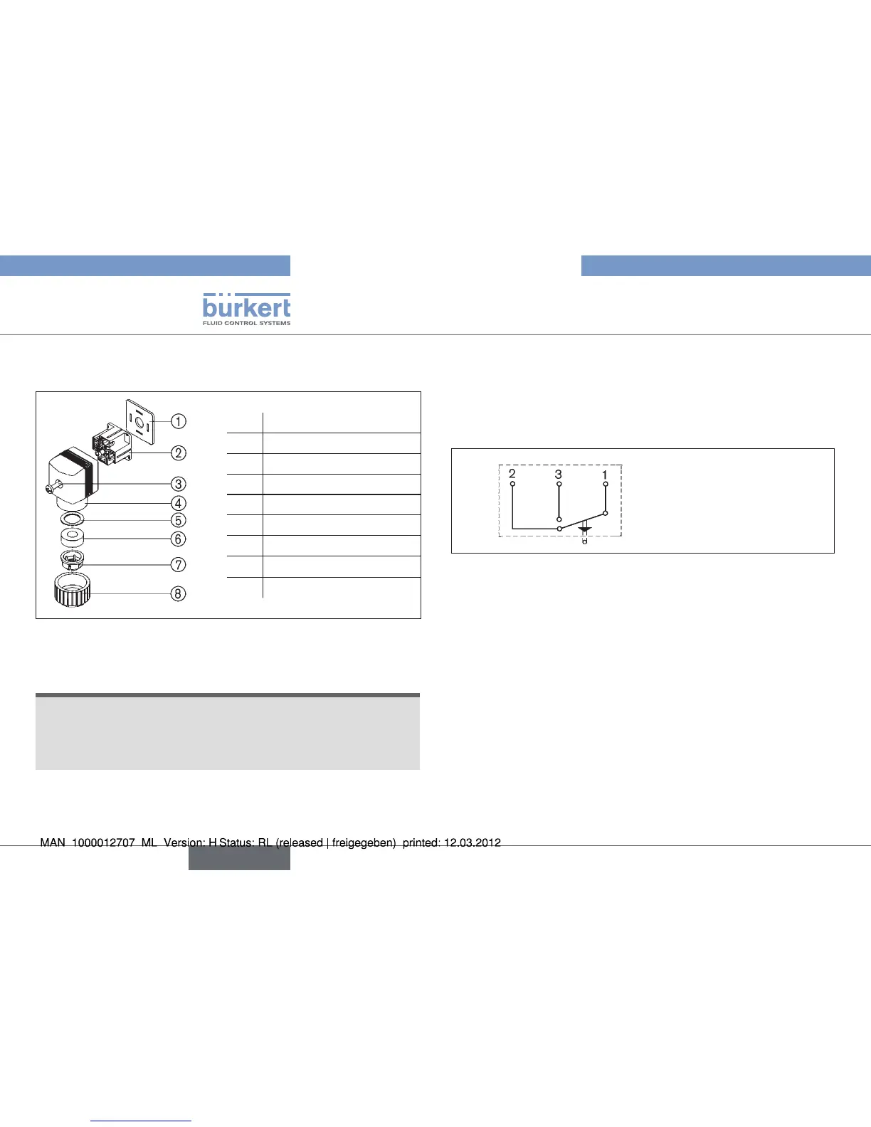
Option: Electrical position repeater
(see “Fig. 11: Connection of the appliance socket”).
1 Flange sealing
2 Contact insert
3 Cap screw
4 Cap
5 Pressure ring
6 Flat seal
7 Collet
8 Coupling nut
Fig. 11: Connection of the appliance socket
Loosen cap screw
→ ③ on the appliance socket and remove.
Carefully remove the contact insert and take care to ensure that •
the connector lugs do not become buckled.
Loosen screw in the cap
→ ④ and remove contact insert ②.
Lead cable through coupling nut
→ ⑧.
Make connection as per circuit diagram
→
(see „Fig. 12: Electrical WAFitsching“).
Max. rating:
→
5 A at 250 V AC
0,25 A at 250 V DC.
Assignment: 1. Input
2. Break contact
3. Make contact
Electrical WAFitschingFig. 12:
Place contact insert
→ ② in the cap ④ and screw on.
Screw on appliance socket with cap screw
→ ③, assuring proper
seating of the flat seal ⑥.
Test valve for function and leaktightness.
→
english