24
Installation and wiring
Type 8228
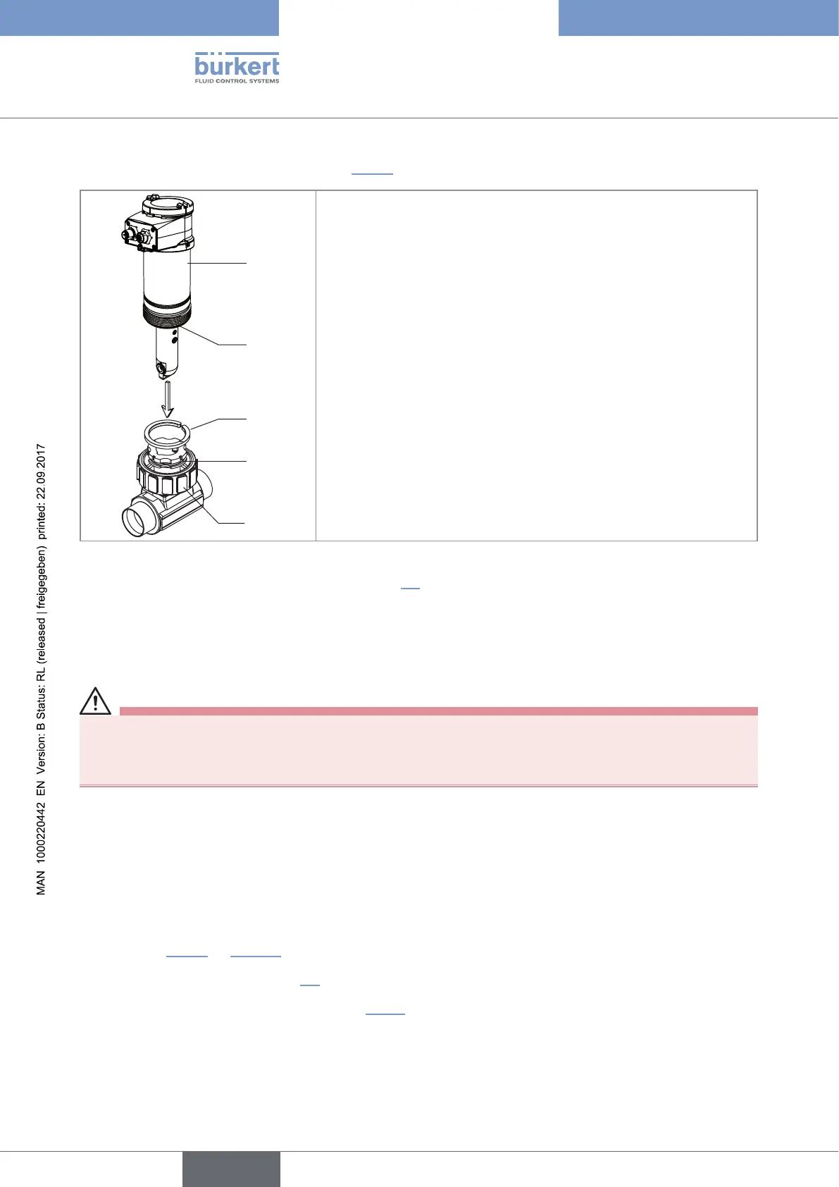
→ Install the device in the fitting as shown in Fig. 10:
1
2
3
4
5
→ Make sure the seal (mark 2) is on the conductivity sensor.
→ Make sure the material of the seal is compatible with the fluid to be
measured.
→ Put the nut (mark 5) on the fitting.
→ Put the snap ring (mark 3) into the groove (mark 4).
→ Engage the device (mark 1) into the fitting.
→ Screw the nut (mark 5) manually on the device.
Fig. 10: Installation of a 8228 with G2'' process connection into the S020 fitting
→ Wire the device according to instructions in chap. 8.4.
8.3 Installing a 8228 with a 2'' clamp process connection
in the pipe
DANGER
Risk of injury if the stainless steel adapter of the device is loose.
A device with a clamp connection is not tight if the adapter is loose.
▶ Do not loosen the adapter of the device.
The device is installed in a pipe as of DN32.
→ Choose a location on the pipe such as:
- the building of air bubbles is prevented,
- the sensor is completely and continuously immerged in the fluid.
→ Install in the pipe a fitting with a 2'' clamp connection according to ASME BPE for the device.
→ Mount the fitting on the pipe obeying the instructions of the Operating Instructions of the fitting used (not
delivered). Fig. 11 on page 25 shows an example for the fitting (mark 5).
→ Fit the display module (see chap. 7.4) to calibrate the conductivity sensor and to parameter the device.
→ Calibrate the conductivity sensor (see chap. 9.12.4).
English