26
Installation and wiring
Type 8228
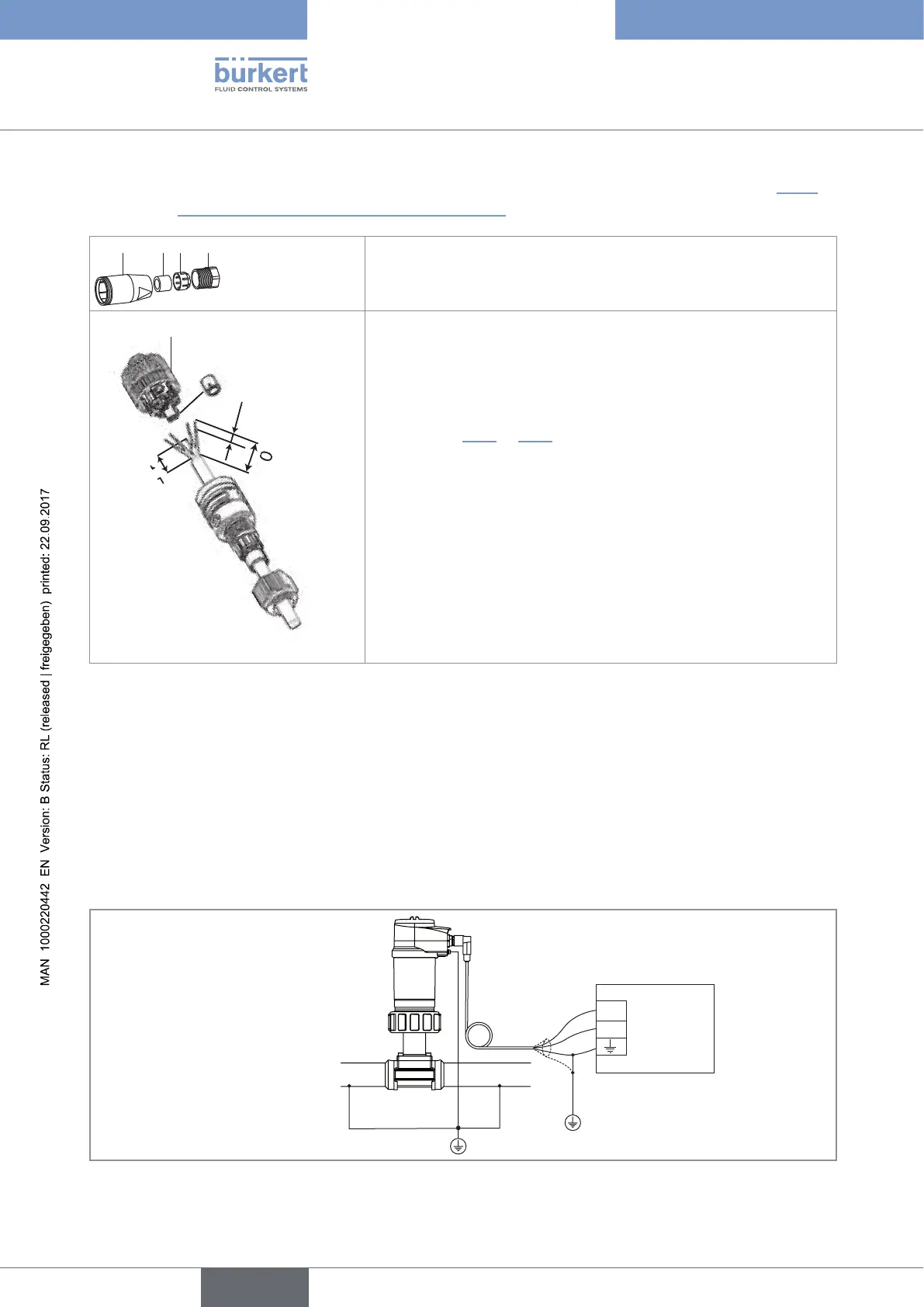
8.4.1 Assembling the male or female connector (see chap. "11
Accessories and spare parts")
4 3 2 1
→ Unscrew the nut [1] on the body [4].
→ Insert the cable into the nut [1], the cable clamp [2] and the seal
[3], and then into the body [4].
5,5
11,5
20
5
→ Strip 20 mm of the cable.
→ Cut the central wire (earth) so that its length is equal to 11.5 mm.
→ Expose 5.5 mm of the wires on the stripped cable.
→ Put each wire into the appropriate terminal of the terminal block [5]
(see chap. 8.3.3 or 8.3.4).
→ Tighten the terminal block [5] wired to the body [4].
→ Tighten the connector nut [1].
Fig. 12: Assembling the M12 multi-pin connector (not provided)
8.4.2 Making the installation equipotential
To ensure the equipotentiality of the installation (power supply - device - medium):
→ Connect together the various earth spots in the installation to eliminate the potential differences that may
occur between different earthes.
→ Observe faultless earthing of the shield of the power supply cable, at both ends.
→ If the device is installed on plastic pipes, earth together the metallic instruments such as pumps or valves, that
are as close as possible to the device.
12-36 V DC
+
-
Metal pipe
Power supply
Fig. 13: Equipotentiality skeleton diagram with pipes in metal
English