25
Installation and wiring
Type 8228
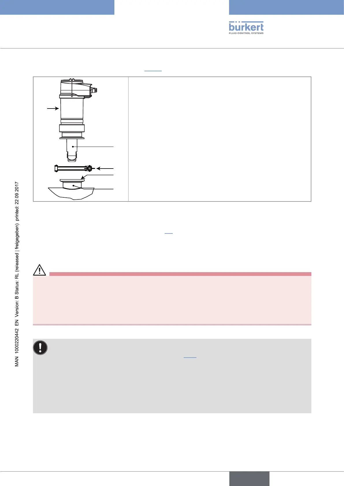
→ Install the device in the fitting as shown in Fig. 11.
→ Select a seal (mark 4) that is compatible with the 2'' clamp con-
nection of the device and with the fluid.
→ Put the seal (mark 4) on the fitting (mark 5).
→ Insert the device (mark 1) in the fitting (mark 5):
- the electrical connections must be parallel to the pipe,
- the sensor (mark 2) must be positioned in the fluid vein.
→ Tighten the clamp collar (mark 3) by hand.
Fig. 11: Installation of a 8228 with 2'' clamp connection in the pipe
→ Wire the device according to instructions in chap. 8.4.
8.4 Wiring the device
DANGER
Risk of injury due to electrical voltage.
▶ Shut down the electrical power source of all the conductors and isolate it before carrying out work on the
system.
▶ All equipment connected to the device shall be double insulated with respect to the mains according to the
standard IEC 61010-1:2010.
▶ Observe all applicable accident protection and safety regulations for electrical equipment.
• Use a filtered and regulated 12-36 V DC power supply.
• Make sure the installation is equipotential (see chap. 8.4.2).
• Use shielded cables with a temperature limit of 80 °C minimum.
• Do not install the connection cables near high voltage or high frequency cables; If this cannot be
avoided, observe a min. distance of 30 cm.
• Protect the power supply of the device with a 100 mA time-delay fuse and a switch.
• Protect the power supply of each transistor output with a 750 mA fuse.
English