62
Operating and commissioning
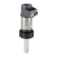
Type 8228
When the device generates a "warning" or an "error" event:
→ go into the “Info” menu to read the cause of the event generation.
→ and/or go into the “Sensor” function of the Diagnostic menu to read the measured temperature value.
→ then make sure the built-in temperature probe is working correctly by measuring a fluid with a known temper-
ature. If the temperature probe is faulty, return the device to Bürkert.
→ if the temperature probe is not the cause of the problem, check the process.
• The "warning" event can be associated to one or both transistor outputs (see chap. 9.11.10, function
"Output.TR1" or "Output.TR2").
• The "error" event can be associated to one or both current outputs (see chap. 9.11.9, function "Output.
AC1" or "Output.AC2").
• See also chap. "10.3 Solving a problem".
ACTIVATE: choose whether or not to activate monitoring of the fluid temperature.
TEMPERATURE: read the fluid temperature measured in real time through the built-in temperature probe.
WARN HI: enter the fluid temperature value above which a “warning” event is generated.
WARN LO: enter the fluid temperature value below which a “warning” event is generated.
ERR HI: enter the fluid temperature value above which an “error” event is generated.
ERR LO: enter the fluid temperature value below which an „error“ event is generated.
9.14 Knowing the Test menu
9.14.1 Modifying the Test menu access code
See chap. 9.9 to access the Test menu.
System
Code 0*** Confirm code 0***
Test
Enter the new code Enter the new code a second
time
If the default code (0000) is entered, the code will not be requested to access the menu.
9.14.2 Checking the outputs functions
See chap. 9.9 to access the Test menu.
• Make sure the "Hold" mode is deactivated (see chap. 9.12.1).
• The
icon is displayed in place of the icon as soon as the check for the correct working of an
output has started. During the check the related output does not react according to the measured
physical value.
Test
Outputs
AC2:
AC1: INPUT
INPUT
TR1: OFF/ON
TR2: OFF/ON
English