50
Operating and commissioning
Type 8228
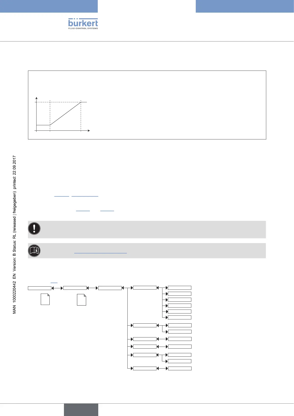
Functions “4mA” and “20mA” are used to define the measurement range for the process value associated with
the current on the 4-20 mA output.
P
1
and P
2
are the values associated with a current of 4 mA or 20 mA respectively:
If P
1
is higher than P
2
, the signal is inverted and the range P
1
-P
2
corresponds to the range for the 20-4 mA
current.
0
4
P
2
P
1
Process value chosen
Fig. 33: 4-20 mA current depending on the process value selected
4mA: choose the value of the process value (previously selected), associated with a current of 4 mA, for each
current output.
20mA: choose the value of the process value (previously selected), associated with a current of 20 mA, for each
current output.
FILTER: choose the level of damping for the fluctuations of the current value for each current output. Three filter
levels are proposed: slow, fast or none. The damping for the current outputs is similar to the damping of the
display (see Fig. 32, chap. 9.11.5).
MODE DIAG.: choose to emit a current of 22 mA on the current output selected when an “error” event related to
diagnostics (see chap. 9.13.2 and 9.13.3) is generated by the device or allow the current output to operate nor-
mally (choose "none").
An "error" event linked to a malfunction of the device is always indicated by the generation of a 22 mA
current, whatever the adjustmant made in the function "MODE DIAG.".
See also chap. "10.3 Solving a problem".
9.11.10 Setting the parameters of the transistor outputs
See chap. 9.9 to access the Parameters menu.
Param
This is
when the
device is be-
ing parame-
tered............
....................
This is
when the
device is be-
ing parame-
tered............
....................
Outputs
TR1 / TR2
PVar:
Low:
INPUT
High:
INPUT
Delay: INPUT
Contact:
CondS
TDSppm
TempC
TempF
CondR
Warning
Mode: Hysteresis
Window
Normally open
Normally closed
If PVar ≠ "warning"
If PVar
≠ "warning"
If PVar
≠ "warning"
English