EasyManuals Logo

CAB Hermes Series User Manual

CAB Hermes Series
71 pages
To Next Page IconTo Next Page
To Previous Page IconTo Previous Page
Page #67 background imageLoading...
Page #67 background image
B-6 cab - Produkttechnik GmbH
Circuit Diagram of Inputs and Outputs
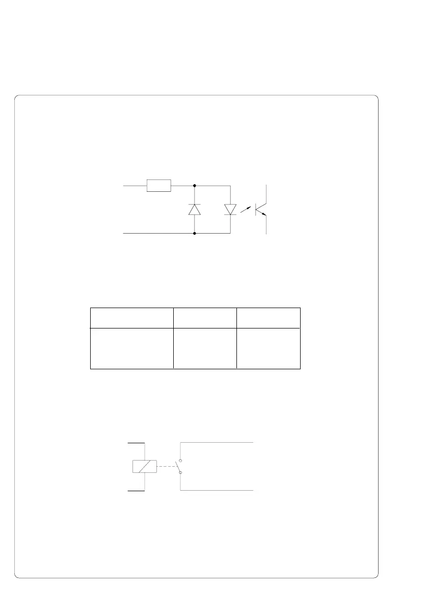
The inputs are optocouplers with a current limiting resistor of 2.4k in the
input circuit.
[IN]
[IN]R
Fig. B-8 Circuit of the inputs
[IN] Pin [IN] Pin [IN]R
Print start 8 15
Label was taken 7 14
External error 6 13
Table B-4 Pairs of input signals
For each signal [IN] there is a separate reverse line [IN]R via the plug
connector. From that the following pairs of signals result :
All outputs are switched by relays which all have one common reverse line
(PIN 10 of the the plug).
[OUT]
Reverse line (Pin10)
Fig. B-9 Circuit of the outputs
Electrical requirements : U
max
= 42 V
I
max
= 100 mA

Table of Contents

Questions and Answers:

Question and Answer IconNeed help?

Do you have a question about the CAB Hermes Series and is the answer not in the manual?

CAB Hermes Series Specifications

General IconGeneral
DisplayLCD with backlight
CutterOptional
DispenserOptional
Print TechnologyThermal Transfer
Resolution203 dpi, 300 dpi, 600 dpi (depending on the model)
InterfacesUSB, Ethernet, Serial
Memory64 MB RAM, 128 MB Flash
Media TypesLabels, continuous media
Supported Barcode TypesData Matrix, QR Code
Max Print Width4.09 inches (104 mm)

Related product manuals