2
2
2-11
2-11
Technical Overview > Controller System > Low-voltage Power Supply > Outline
Technical Overview > Controller System > Low-voltage Power Supply > Outline
■
Failure Detection
Failure Point Cause of Failure
Main Motor In the case that the speed of Motor does not reach the specied speed after the
specied time has passed since the startup of the Main Motor.
Main Fan In the case that the Fan has been locked continuously for the specied period of
time since the startup of the Main Fan Motor.
T-2-6
Low-voltage Power Supply
■
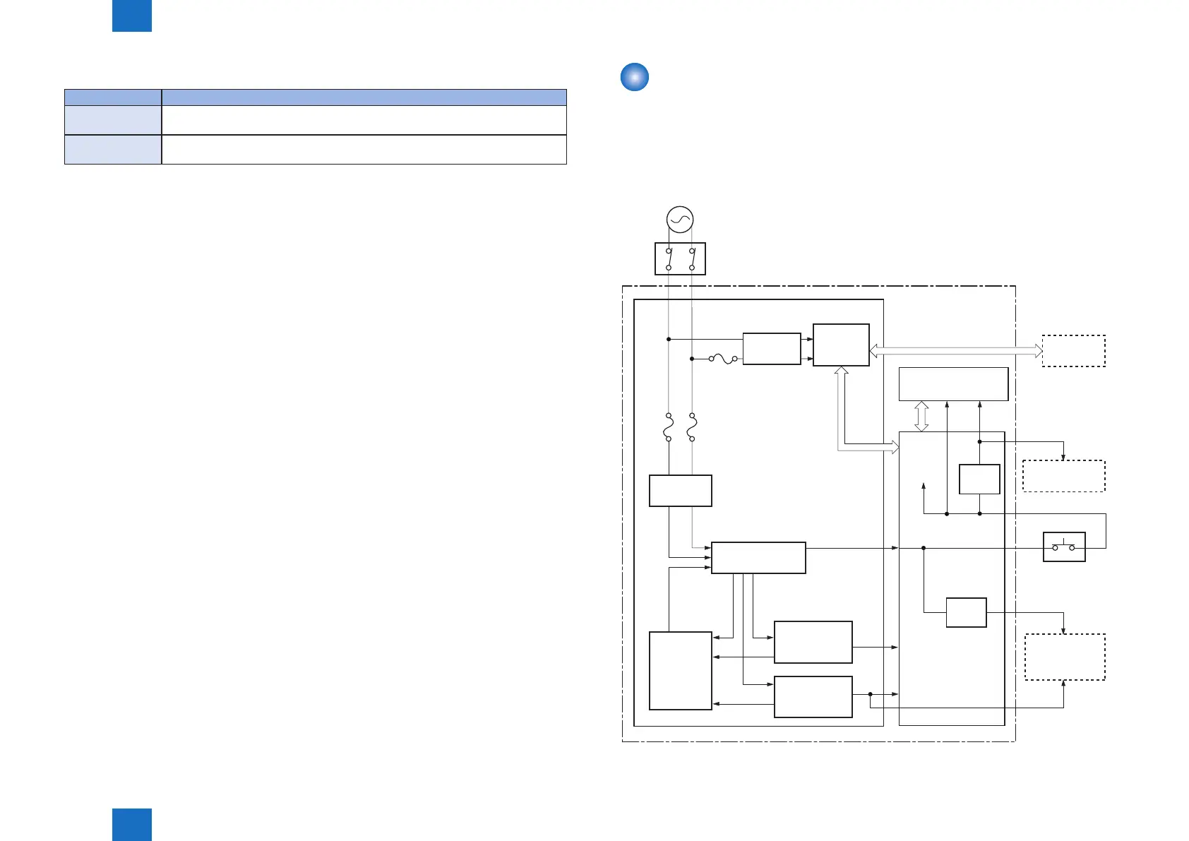
Outline
The Low-voltage power supply converts AC Power from the power receptacle into DC Power
to cover the DC loads.
Block diagram of the Low Voltage Power Supply is shown below.
+5V
+3.3V
+3.3V
+24V
+24U
+24V_S
DOOR
SNS
Noise
filter
FET
+24P1
Fuse
(FU1002)
Fuse
(FU1001)
Door switch
(SW301)
+24V generation
circuit
DC controller
Low-voltage power supply
Engine controller
Fixing
control
circuit
Fixing unit
Main motor, etc.
Main controller
+5V
generation
circuit
+3.3V
generation
circuit
High-voltage
power supply
Noise filter
Protection
circuit
Fuse
(FU101)
FET
Power switch
(SW1,SW11)
F-2-11
 Loading...