49
HMI Configuration
General Overview
The HMI allows the user to change between Manual Mode and Auto Mode as well as view Operating
Information regarding fans, Fan Group Assignments, HMI sensor group assignments, External sensor
assignments, sensor temperatures, and Fault History.
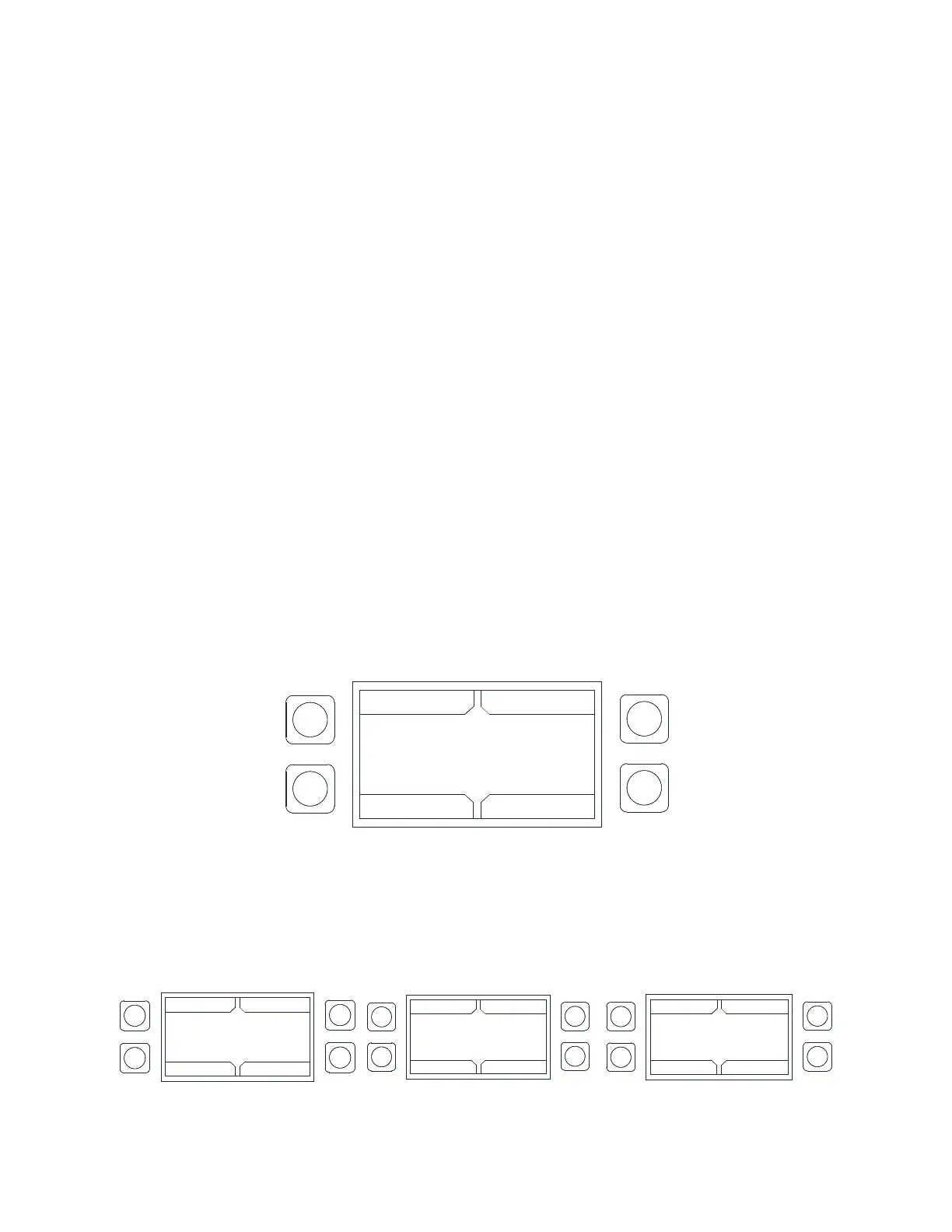
At any point in time, the user can access the HMI configuration screen. This is achieved by simultaneously
pressing both top buttons and holding them for 1 second. When this occurs, the screen will look similar to
the image to the right. To exit this screen, simply press the DISPLAY button.
Also, during initial HMI configuration, each HMI must have a unique Modbus address or HMI number. To
assign this, simultaneously press both bottom buttons and hold them for 1 second. When this occurs, the
user will be able to assign an HMI number to the HMI. Once the HMI number is assigned, press the SAVE
button to exit the screen.
When a fault occurs in the system, an audible alarm is triggered and a message is displayed on the
HMI(s). The Audible Alarm can be silenced by pushing the Mute button that appears on the screen.
The HMI menu system is illustrated on page 51 and allows full access to every configurable parameter in
the HMI. The parameters are factory configured to the specific application. Parameters may need to be
modified to fine-tune automatic operation or to add an HMI or fan to a system after the original setup.
Editing HMI Number and Contrast
To set the HMI number or to adjust the screen contrast, press the bottom two buttons simultaneously on
the HMI faceplate. Use the UP and Down buttons to select the parameter that will be adjusted. Press Enter
to select the highlighted parameter.
Setting the HMI number configures the Modbus address for that HMI.
The user may adjust the contrast setting from 0 to 10. Setting the contrast to 0 is the lowest setting
available, 10 is the highest contrast setting available. The factory default contrast setting is 5.
Figure 40 - HMI Number and Contrast
Input Simulation
Input simulation allows the user to test the fans (Configuration > Advanced Options > Input Simulation).
This will allow the user to enable the 0-10V signal test. You may adjust the voltage signal range from low
(0V) to high (10V).
Figure 41 - Input Simulation
HMI CONFIGURATION
EDIT HMI NUMBER
EDIT HMI CONTRAST
UP
BACK
DOWN
ENTER
HMI CONFIGURATION
EDIT HMI NUMBER
EDIT HMI CONTRAST
UP
DISPLAY
DOWN
ENTER
HMI CONFIGURATION
EDIT HMI NUMBER
EDIT HMI CONTRAST
UP
BACK
DOWN
ENTER
HMI CONFIGURATION
EDIT HMI NUMBER
EDIT HMI CONTRAST
UP
BACK
DOWN
ENABLE