61
Low Voltage BMS Interlock
On the ECPM03 circuit board, near the top left of the board, there are terminals IL1A and IL1B. Closing a
dry contact between these two terminals will turn the fans on and bring all fans to a defined BMS speed.
When a 0-10V DC signal is detected by pin VIN, located on the ECPM03 circuit board, all fans will
modulate between the low voltage and the high voltage speed based on input voltage. The BMS speed is
defined for each fan on the ECPM03 board, which will be discussed later in this manual. Once the contact
is opened up between these two terminals, the HVLS control will enter the mode that it was in previous to
BMS mode.
High Voltage BMS Interlock
There is a high voltage set of terminal blocks inside the enclosure. These blocks are labeled IO1 and H1.
The high voltage BMS interlock should be energized by closing a dry contact placed between terminals H1
and IO1. When this occurs for HVLS applications, the fan(s) will run at the maximum defined VFD speed
until the contact is opened up. Once the contact is opened up between these two terminals, the HVLS
control will enter the mode that it was in previous to BMS mode. When this occurs for General Ventilation
Fan applications (during a fire signal), the fan(s) will run at their maximum defined VFD speed until the
contact is opened up. Once the contact is opened up between these two terminals, the General Ventilation
Fan control will enter the mode that it was in previous to BMS mode.
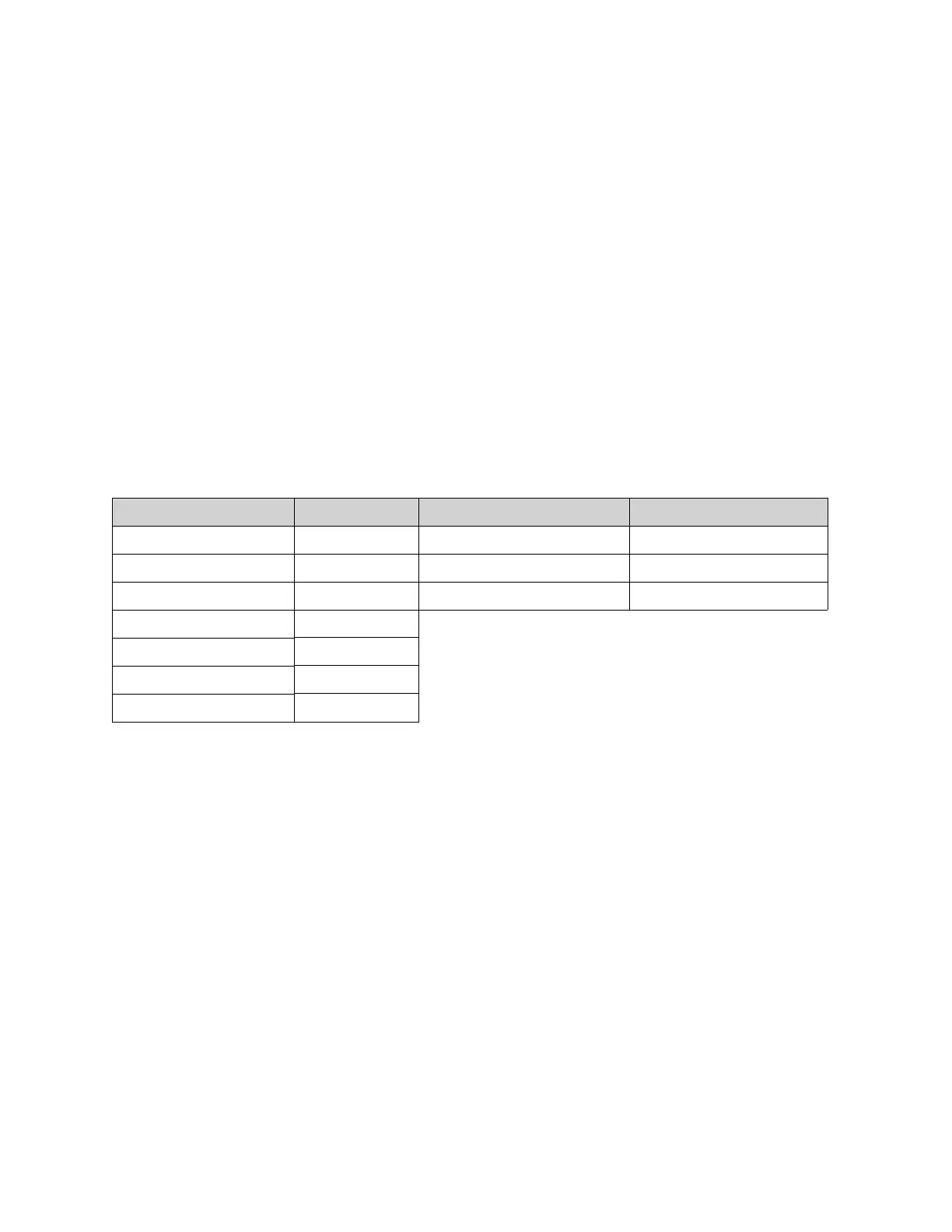
Table 10 - Automatic Mode Operation Summary
Monitoring Points Units Configurable Item Range/Limit
Power Kw Low Voltage Speed BMS Fan Speed
Current Amps High Voltage Speed Max VFD Speed
Speed Hz Temperature Units °F/°C
Motor Voltage Volts
% Load %
Run Time Hours
VFD Temp °F/°C