34
High Voltage Wiring
High voltage wiring consists of the main control panel power and wiring to and from each VFD when the
VFD is panel mounted. If the VFD is remote mounted, VFD power does not need to go to the enclosure.
1. There are multiple electrical connections required for this control. 120V AC, 1 Phase, 15 Amp service
should be wired to terminals H1 and N1 to power the controls. Input power to the variable frequency
drives should be wired to the series of quick disconnect terminal blocks on the side of the enclosure.
Drive input power should match the nameplate on the drive. Output power from the variable frequency
drives is always 3 phase and should match the voltage requirements of the fan motors.
2. All high voltage wiring shall be terminated on the right side of the enclosure on terminal blocks located
on the right-hand side.
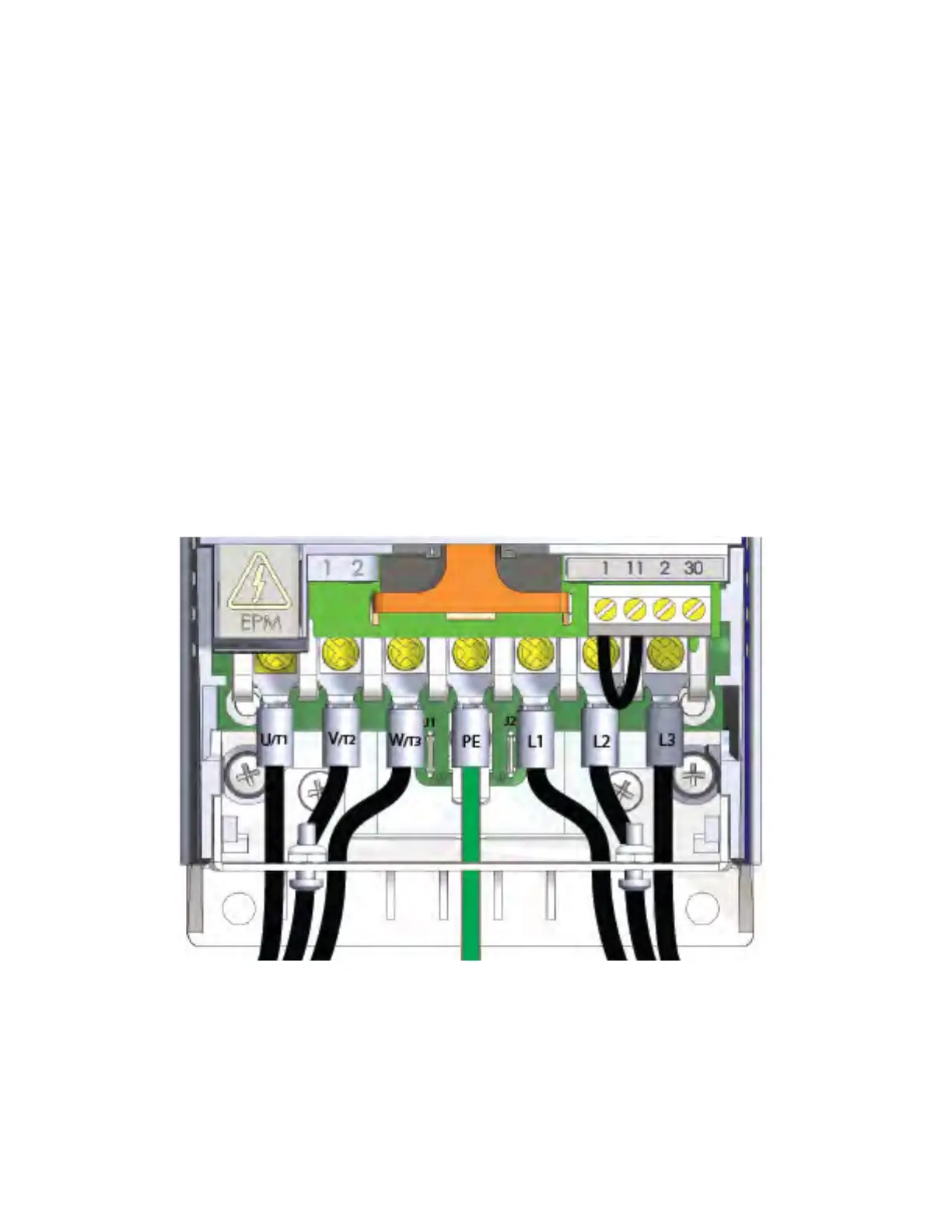
VFD Wiring
When connecting the motor to the VFD, use terminals U/
T1
, V/
T2
, W/
T3
for motor connections. For
connecting building power:
• Use L1, L2, and L3 for building connections with 3-phase inputs
• Use only L1 and L2 for 240 volt single-phase inputs
• Use only L1 and N for 120 volt single-phase inputs
Reference Figure 30 through Figure 32 for common VFD wiring.
Figure 30 - VFD Wiring (3-Phase)