57
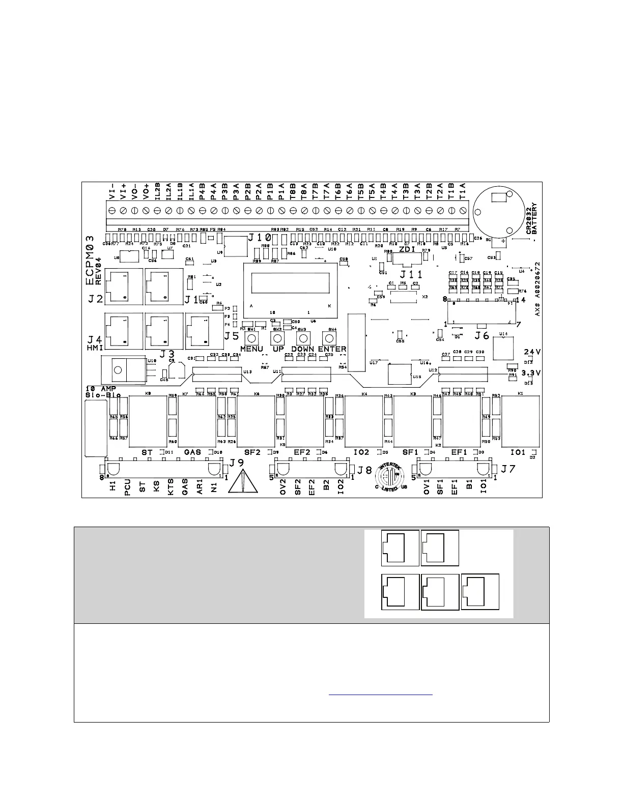
ECPM03 Board
ECPM03 is the main control of the system. It receives all of the digital and analog inputs, and delivers all
digital outputs for external devices.
NOTE: Not all pins or electrical features may be used with your electrical control package. Verify
with wiring schematics and/or HMI settings.
Connector Descriptions
RJ45 Connectors
J1, J2 - Modbus master network connectors, feed through RJ45s, which conform to the Modbus pin-out
for RS485 2 wire differential Modbus RTU standard. J1 and J2 are utilized for Comm Module and external
BMS interface. No field wires should be connected to J1 or J2.
J3, J4, J5: Modbus slave network connectors feed through RJ45s, which conform to the Modbus pin-out
for RS485 2 wire differential Modbus RTU standard. See http://www.modbus.org
. Modbus communication
is not configured for third party integration without additional components. All network, PCUAFM, HMI,
and VFDs report through J3, J4 and J5. The order of connection is irrelevant.