58
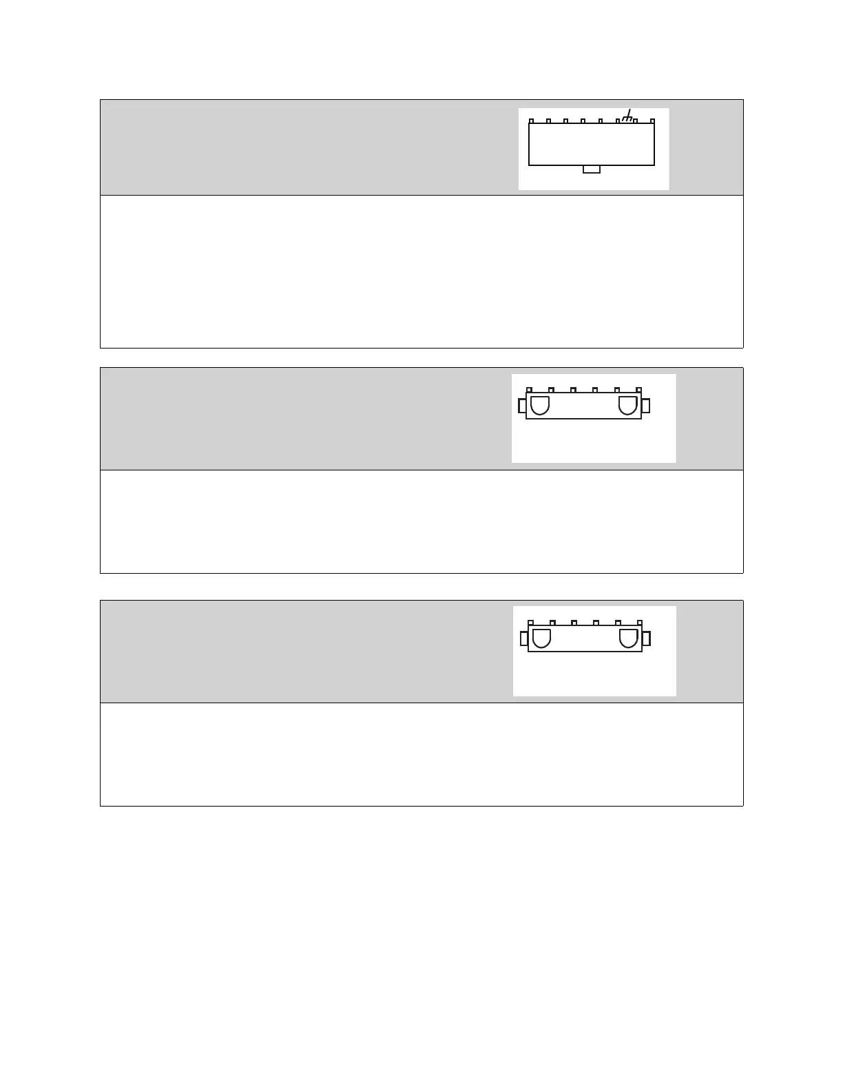
Connector J6 contains factory only wiring for low
voltage connections
Pin 1 - 24V DC power input (positive side) to the board.
Pin 2 through pin 7 - Each open collector relay output (RO) sources 100 mA max and is suitable for driv-
ing 24V DC relays or indicator lamps.
Pin 8 through pin 12 - 4-20 mA current inputs. 150 Ohm impedance to 24V DC ground pin 14.
Pin 13 - Chassis ground connection, this pin connects to the 24V DC ground through a paralleled 1000pf
2000V capacitor and a 100k Ohm 1/4W resistor.
Pin 14 - 24V DC power input (negative side) to the board. Ground or common side of the low voltage cir-
cuitry.
Connector J7 contains 120V AC control connector for
factory only wiring
Pin 1 - (IO1) output and input, this pin can source 120V AC and detect the presence of 120V AC.
Pin 2 - (B1) input, this pin can detect the presence of 120V AC.
Pin 3 - (EF1) output and input, this pin can source 120V AC and detect the presence of 120V AC.
Pin 4 - (SF1) output, this pin can source 120V AC.
Pin 5 - (OV1) input, this pin can detect the presence of 120V AC.
Connector J8 contains 120V AC control connector for
factory wiring
Pin 1 - (IO2) output and input, this pin can source 120V AC and detect the presence of 120V AC.
Pin 2 - (B2) input, this pin can detect the presence of 120V AC.
Pin 3 - (EF2) output and input, this pin can source 120V AC and detect the presence of 120V AC.
Pin 4 - (SF2) output, this pin can source 120V AC.
Pin 5 - (OV2) input, this pin can detect the presence of 120V AC.