62-12259 2–12
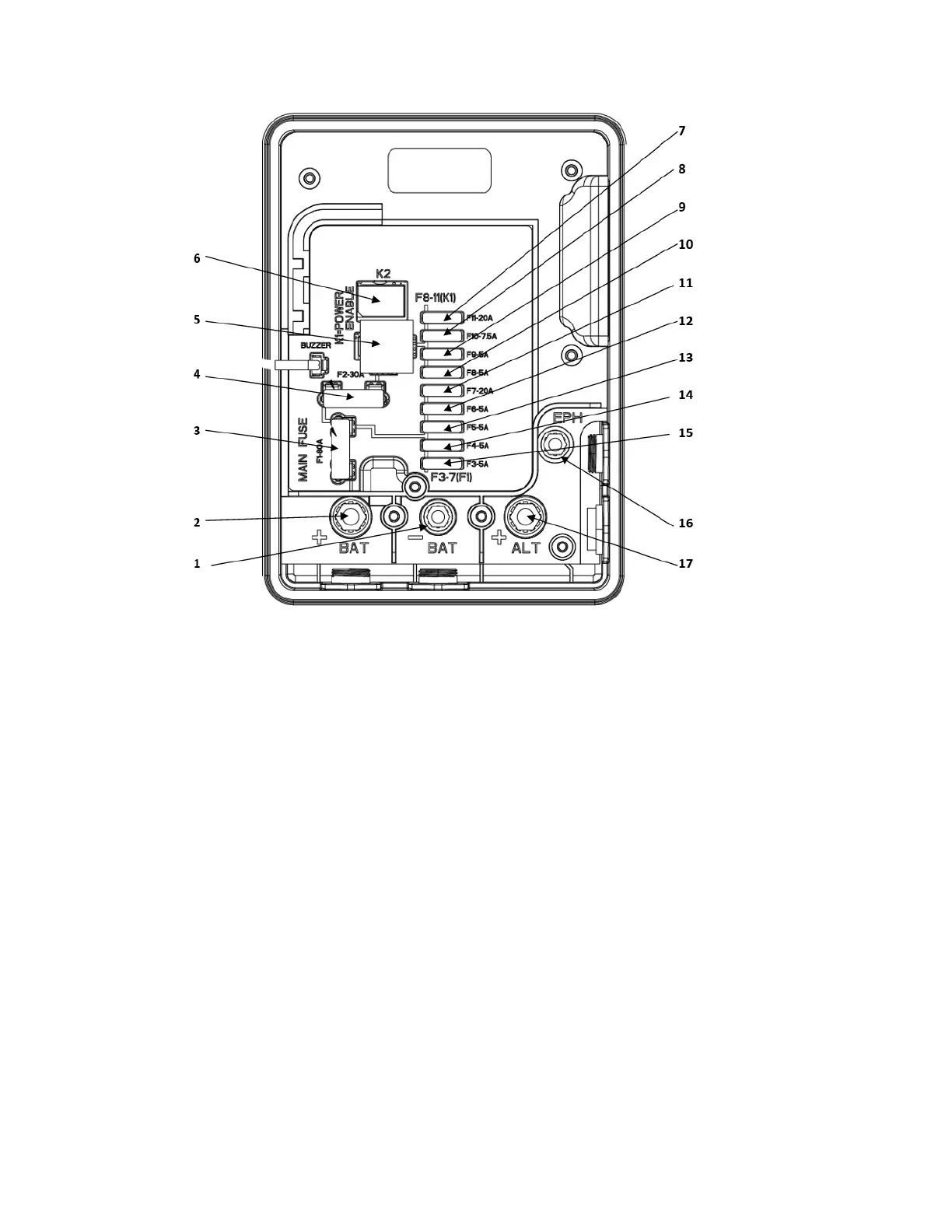
Figure 2.5 Power Module
1. Battery Negative
2. Battery Positive
3. F1 80 amp - Main Fuse
4. F2 30 amp - Power Enable Relay Fuse
5. Diesel / Electric Relay (Only used for Fuel Heat Option)
6. Power Enable Relay
7. F11 20 amp - System Loads Fuse
8. F10 7.5 amp - CCB / EES Fuse
9. F9 5 amp - Light Bar / Satellite Power Fuse
10. F8 - Not Used
11. F7 20 amp - Fuel Heat Option Fuse
12. F6 5 amp - Logic Power Fuse
13. F5 5 amp - Microprocessor / Stepper (MSM) Fuse
14. F4 7.5 amp - Engine Control Unit / Remote Panel Fuse
15. F3 5 amp - Battery Guard Fuse
16. Engine Preheat
17. Alternator Positive
2.5.4.1 Power Module
The Power Module (PM - see Figure 2.5) is responsible for distribution of power from the battery to the
system components, when starting, and then from the battery charger to the system components and to
the battery (for charging) once power is available.
The module houses the system relays, low voltage fuses, control FETs and the DC current transformer.
The current transformer provides a reading of the total 12 VDC system current draw (amps) to the Micro-
processor/Stepper Module.