62-12259 2–18
2.6.3 Remote Temperature Sensor
The unit is provisioned to connect remote temperature sensors (REMSN1, REMSN2 and REMSN3) through the
REM connector located in the evaporator section.
The system may be configured to display the sensor reading in the Unit Data and to record the sensor reading in
the data recorder. A user specified name may be configured for each sensor. This name will be displayed, rather
than the default Remote Sensor #1, #2 or #3, name in the unit data list.
2.6.4 Fuel Level Sensor
An optional fuel level sensor (Figure 8.8) supplies an input signal to the control system as to the percentage of fuel
remaining in the fuel tank. The control system will activate alarm 00001 Low Level Fuel Warning when the level
reaches 15%, and (if configured to do so) shuts the engine down when the level reaches 10%. The alarm is auto-
matically cleared when the level is brought above 25%. The fuel tank level is displayed in Unit Data.
2.6.5 Fuel Heater
The electric fuel heater (Figure 2.2) applies heat to fuel in the fuel filter. Heating the fuel dissolves/prevents paraffin
wax crystals (and ice) that form when diesel fuel is chilled thus enabling the water separator to work more effi-
ciently and to prevent the filter from plugging with wax and/or ice crystals.
When the ambient air sensor is reading 77°F (25°C) or lower, the control system will enable this circuit. Also, the
heater is fitted with an internal temperature switch (FHTS) which will close on a temperature fall to energize the
heater element, and open on a temperature rise to de-energize the heater element.
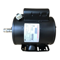
2.6.6 Electric Fuel Pump
The electric fuel pump (Figure 8.7) is mounted at the fuel tank location and assists the engine mounted mechani-
cal pump in transferring fuel from the tank to the engine. The pump is activated by the control system.
2.6.7 Remote Panel
The unit may be fitted with an optional remote control panel. The remote panel, which is very similar to the display
module, displays compartment setpoints, compartment temperatures and operating modes (heat, cool or defrost).
The setpoint may be modified and the unit may be started and stopped using the remote panel.
This compact remote panel can be mounted to suit the individual operator’s preferences - on the front bulkhead, or
in the compartment (including in the wall itself). Remote Panel keys, soft keys and alarm indicators are in the same
locations as the main APX display module.
2.6.8 Water in Fuel (WIF) Sensor
The Water in Fuel (WIF) sensor continuously monitors the level of water collected in the water bowl of the fuel filter
When the trigger volume of water is reached in the bowl, sensor resistance changes and the APX control system
triggers a notification alarm at the display to drain the water bowl. Trigger volume occurs when there is approxi-
mately 200ml of water in the approximately 350ml water collection bowl.
 Loading...