2–7 62-12259
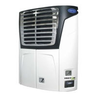
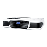
2.3 Condensing Section
The condensing section (see Figure 2.1 and Figure 2.2) consists of an engine-generator drive package, compres-
sor, condenser fans, condenser, radiator, economizer, refrigerant controls, defrost air switch, piping, wiring, and
associated components. The condensing section may also be equipped with an AutoFresh Air Exchange.
The engine-generator drive package (see Figure 2.2) includes the engine, generator, air cleaner, muffler, coolant
system, fuel system, engine oil filter system and engine sensors.
2.3.1 Engine
The engine is a four-cylinder diesel which gives excellent fuel economy. It drives the compressor directly through a
nylon dive gear and adapter. The adapter also includes a V-belt sheave which drives the power train. The engine
cooling system consists of the radiator (which is mounted with the condenser coil) and coolant overflow bottle.
The engine is equipped with:
• Glow plugs, which provide easy starting characteristics.
• Spin-on engine oil filter and a spin-on or suction side fuel filters for easier filter changes.
• The fuel filter may also be equipped with a thermostatically controlled fuel heater.
Refer to Section 2.7 for engine data.
2.3.2 Engine Air System
The air cleaner prolongs the life and performance of the engine by preventing dirt and grit from getting into the
engine and causing excessive wear on all operating parts. It is the responsibility of the operator to give the air
cleaner equipment regular and constant attention in accordance with the instructions. An air cleaner service
indicator is connected at the outlet. Its function is to indicate when the air cleaner filter element requires
replacement. (Refer to Section 8.5.8).
The system may be fitted with an intake air temperature sensor (IAT) and a manifold absolute pressure transducer
(MAP). These sensors are installed when Carrier Transicold factory monitoring of the air system is required.
2.3.3 After Treatment System
2.3.3.1 Diesel Oxidation Catalyst System
The diesel oxidation catalyst (DOC) system consists of a DOC. The DOC system burns particulate matter
(PM) such as soot, contained in exhaust gas and performs after-treatment on it. The PM is combusted and
changed into carbon dioxide and water by chemical reaction. The carbon dioxide is released to the atmo-
sphere.
2.3.4 Engine Controls
2.3.4.1 Engine Control Unit (ECU)
The engine ECU controls the injection amount, injection timing, injection rate and injection pressure during
fuel injection. The ECU sends inputs to each actuator based on information received from each sensor.
Software is pre-programmed.
2.3.4.2 Atmospheric Pressure Sensor
The Atmospheric Pressure sensor detects atmospheric pressure. The output signal is sent to the engine
ECU. The Atmospheric Pressure sensor is built into the ECU and is non-serviceable.
2.3.4.3 Crankshaft Position Sensor
The Crankshaft Position sensor detects the angular position of the crankshaft. The ECU calculates the pis-
ton position and engine speed based on the signal detected by the crankshaft position sensor. Also know
as Ne sensor in DiagMaster, the sensor operates on 5V.
2.3.4.4 Camshaft Position Sensor
The Camshaft Position sensor detects the angular position of the camshaft. The ECU calculates the piston
position based on the signal detected and generates AC voltage, which is rectified and output to the
engine ECU. The sensor, also known as the G sensor in DiagMaster, operates on 5V.