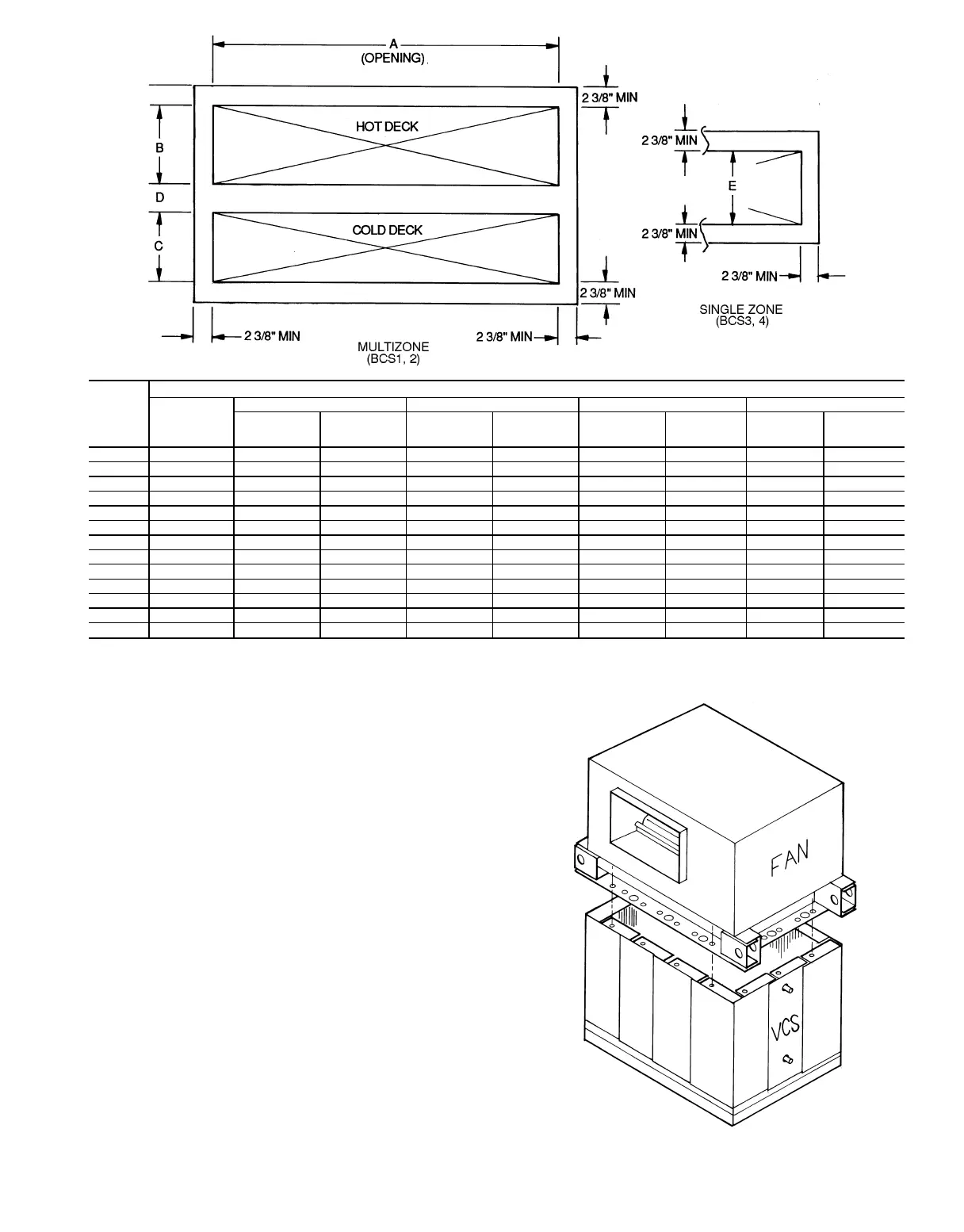
Vertical Draw-Thru Units — Size 26-61 vertical units
that exceed the 108-in. maximum height are shipped with
the fan out of its operating position on the same skid with
the vertical coil section. Install the fan section as follows:
1. Remove the shipping plates holding the fan and coil sec-
tions together and the lag screws holding the sections to
the skid.
2. Attach the
1
⁄
4
-in. thick by 1
1
⁄
4
-in. wide gray gasket sup-
plied with the unit to the top perimeter of the vertical coil
section.
3. Rig the fan section using the bottom lifting brackets and
place it on top of the coil section; see Fig. 20. Align the
larger set of holes in the fan base rail on the screw heads
in the perimeter of the vertical coil section; align the smaller
holes in the fan base rail with the holes in the coil sec-
tion. At installation, the upstream lifting bracket must be
removed if there is a connection flange preceding the ver-
tical coil section.
4. Fasten all 4 sides of the fan section to the coil section
with the
1
⁄
4
-14 by
3
⁄
4
-in. long sheet metal screws
provided.
39T
UNIT
SIZE
DIMENSIONS (ft-in.)
A
(Opening)
BCDE
BCS1
Horizontal
Discharge
BCS2
Vertical
Discharge
BCS1
Horizontal
Discharge
BCS2
Vertical
Discharge
BCS1
Horizontal
Discharge
BCS2
Vertical
Discharge
BCS3
Horizontal
discharge
BCS4
Vertical
Discahrge
07 4- 0
13
⁄
16
0-10
1
⁄
8
0-9
13
⁄
16
0- 7
7
⁄
8
0-9
13
⁄
16
0-3
3
⁄
8
0-1
9
⁄
16
0-9
7
⁄
16
0-9
7
⁄
16
09 4- 4
3
⁄
4
0-10
1
⁄
8
0-9
13
⁄
16
0- 7
7
⁄
8
0-9
13
⁄
16
0-3
3
⁄
8
0-1
9
⁄
16
0-9
7
⁄
16
0-9
7
⁄
16
11 5- 0
5
⁄
8
0-10
1
⁄
8
0-9
13
⁄
16
0- 7
7
⁄
8
0-9
13
⁄
16
0-3
3
⁄
8
0-1
9
⁄
16
0-9
7
⁄
16
0-9
7
⁄
16
13 5- 8
1
⁄
2
0-10
1
⁄
8
0-9
13
⁄
16
0- 7
7
⁄
8
0-9
13
⁄
16
0-3
3
⁄
8
0-1
9
⁄
16
0-9
7
⁄
16
0-9
7
⁄
16
17 6- 0
7
⁄
16
1- 2
1
⁄
16
1-1
13
⁄
16
0-11
13
⁄
16
1-1
13
⁄
16
0-3
3
⁄
8
0-1
9
⁄
16
0-9
7
⁄
16
1-1
3
⁄
8
21 6- 4
3
⁄
8
1- 2
1
⁄
16
1-1
13
⁄
16
0-11
13
⁄
16
1-1
135
⁄
16
0-3
3
⁄
8
0-1
9
⁄
16
0-9
7
⁄
16
1-1
3
⁄
8
26 7- 0
1
⁄
4
1- 2
1
⁄
16
1-1
13
⁄
16
0-11
13
⁄
16
1-1
135
⁄
16
0-3
3
⁄
8
0-1
9
⁄
16
0-9
7
⁄
16
1-1
3
⁄
8
32 7- 4
3
⁄
16
1- 6 1-5
5
⁄
16
1- 5
5
⁄
16
1-5
5
⁄
16
0-4
1
⁄
8
0-2
3
⁄
8
1-5
5
⁄
16
1-5
5
⁄
16
39 8- 0
1
⁄
16
1- 6 1-5
5
⁄
16
1- 5
5
⁄
16
1-5
5
⁄
16
0-4
1
⁄
8
0-2
3
⁄
8
1-5
5
⁄
16
1-5
5
⁄
16
49 8-11
7
⁄
8
1- 9
15
⁄
16
1-9
1
⁄
4
1- 9
1
⁄
4
1-9
1
⁄
4
0-4
1
⁄
8
0-2
3
⁄
8
1-9
1
⁄
4
1-9
1
⁄
4
61 9-11
11
⁄
16
1- 9
15
⁄
16
1-9
1
⁄
4
1- 9
1
⁄
4
1-9
1
⁄
4
0-4
1
⁄
8
0-2
3
⁄
8
1-9
1
⁄
4
1-9
1
⁄
4
74 11- 3
7
⁄
16
2- 1
7
⁄
8
2-1
3
⁄
16
2- 1
3
⁄
16
2-1
3
⁄
16
0-4
1
⁄
8
0-2
3
⁄
8
2-1
3
⁄
16
2-1
3
⁄
16
92 11- 3
7
⁄
16
2- 1
7
⁄
8
2-1
3
⁄
16
2- 1
3
⁄
16
2-1
3
⁄
16
0-4
1
⁄
8
0-2
3
⁄
8
2-1
3
⁄
16
2-1
3
⁄
16
Fig. 19 — Blow-Thru Duct Attachment Surfaces, BCS1-4
VCS — Vertical Coil Section
Fig. 20 — Fan Installation — Vertical Draw-Thru Unit
35