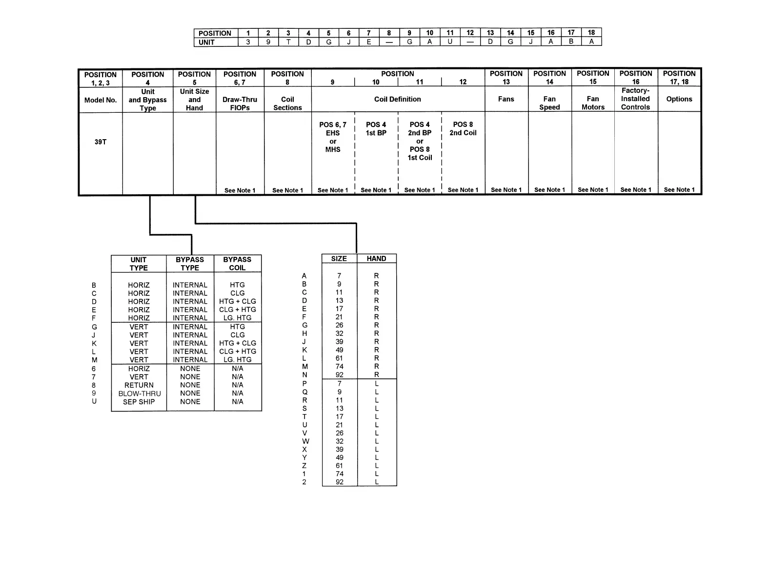
Fig. 1 — Unit Nomenclature
LEGEND
AHU — Air Handling Unit
BP — Bypass
CLG — Cooling
EHS — Electric Heating Coil
FIOP — Factory-Installed Option
HORIZ — Horizontal
HTG — Heating
L—Left-Hand
LG HTG — Long Heating
MHS — Medium Heating Coil
N/A — Not Available
POS — Position
R—Right-Hand
SEP SHIP — Separate Shipped
VERT — Vertical
NOTES:
1. Contact your Carrier sales representative for the
AHU Builder™
program.
2. See Table 1 on page 3 for component descriptions and recommended section
sequences.
3. All components have individual base rails.
4. Connection flanges are supplied between all components.
5. Hand refers to fan motor location or coil header location when facing compo-
nent inlet. For components with one access door, hand also refers to door lo-
cation when facing component inlet. Motor, header, and door hand must be the
same in factory-assembled unit.
4