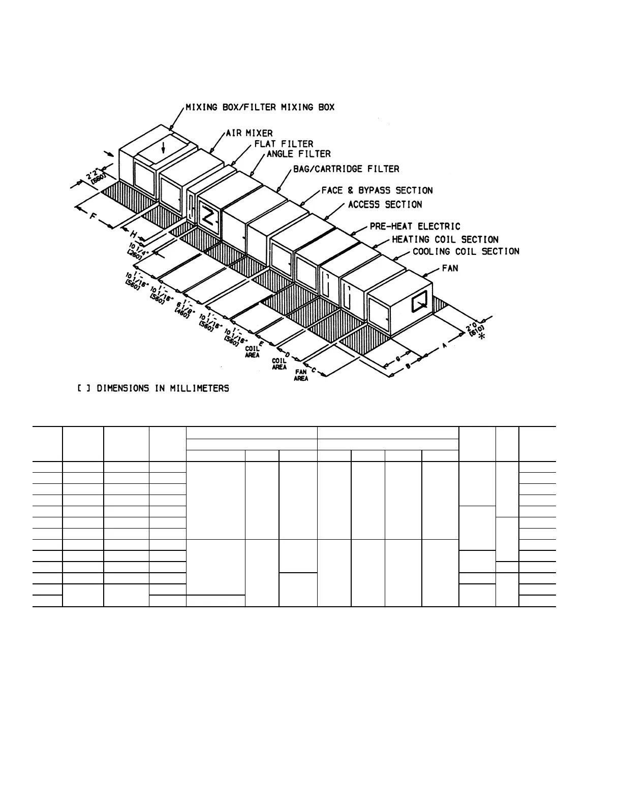
Service Clearance — When planning the placement
of the unit, ensure adequate space for service access. Typical
service operations can require removing the coils and filters
and accessing the motor and damper linkage. See
Fig. 10-13 for recommended clearances.
Drain Positioning — To prevent build-up of conden-
sate in the drain pan and ensure proper operation of the drain
system, position the unit so that condensate is properly trapped.
Refer to the Condensate Drain section on page 65 in the
Installation section.
Service Area Dimensions (ft-in.)
39T
UNIT
SIZE
ABC
DE
FGHCooling Coil Section Heating Coil Section
LCS1, BCC2 FBC1 MCS1 MHS1 BPH1 FBH1 FBH2
07 4-5
11
⁄
16
5- 6
5
⁄
8
2-5
15
⁄
16
1-6
1
⁄
8
2-9
7
⁄
8
1-6
1
⁄
8
1-2
3
⁄
16
1-2
3
⁄
16
1-5
15
⁄
16
3-1
13
⁄
16
2-5
15
⁄
16
2-0
2-5
15
⁄
16
09 4-9
5
⁄
8
5-10
9
⁄
16
2-9
7
⁄
8
2-5
15
⁄
16
11 5-5
1
⁄
2
6- 6
1
⁄
2
2-9
7
⁄
8
2-5
15
⁄
16
13 6-1
3
⁄
8
7- 2
3
⁄
8
3-1
13
⁄
16
3-1
13
⁄
16
17 6-5
1
⁄
4
7- 6
1
⁄
4
3-5
3
⁄
4
3-1
13
⁄
16
3-1
13
⁄
16
21 6-9
1
⁄
4
7-10
3
⁄
16
3-9
11
⁄
16
2-2
3-5
3
⁄
4
26 7-5
1
⁄
16
8- 6 4-1
5
⁄
8
3-5
3
⁄
4
32 7-9 8-10 4-5
9
⁄
16
3-1
13
⁄
16
4-5
9
⁄
16
1-6
1
⁄
8
1-6
1
⁄
8
1-6
1
⁄
8
2-9
7
⁄
8
3-5
3
⁄
4
4-1
5
⁄
8
39 8-4
7
⁄
8
9- 5
7
⁄
8
4-9
1
⁄
2
3-5
3
⁄
4
4-5
9
⁄
16
49 9-4
11
⁄
16
10- 5
11
⁄
16
5-5
3
⁄
8
2-9 4-5
9
⁄
16
61 10-4
9
⁄
16
11- 5
9
⁄
16
6-1
3
⁄
16
1-10
1
⁄
16
4-1
5
⁄
8
3-1
5-1
7
⁄
16
74
11-8
1
⁄
4
12- 9
1
⁄
4
6-5
3
⁄
16
4-5
9
⁄
16
5-5
3
⁄
8
92 7-8
15
⁄
16
3-5
3
⁄
4
6-1
3
⁄
16
*Service area required for access door(s) on side opposite hand and for coil removal.
NOTE: See Table 1 for component description.
Fig. 10 — Service Area Requirements, Horizontal Draw-Thru Units
28