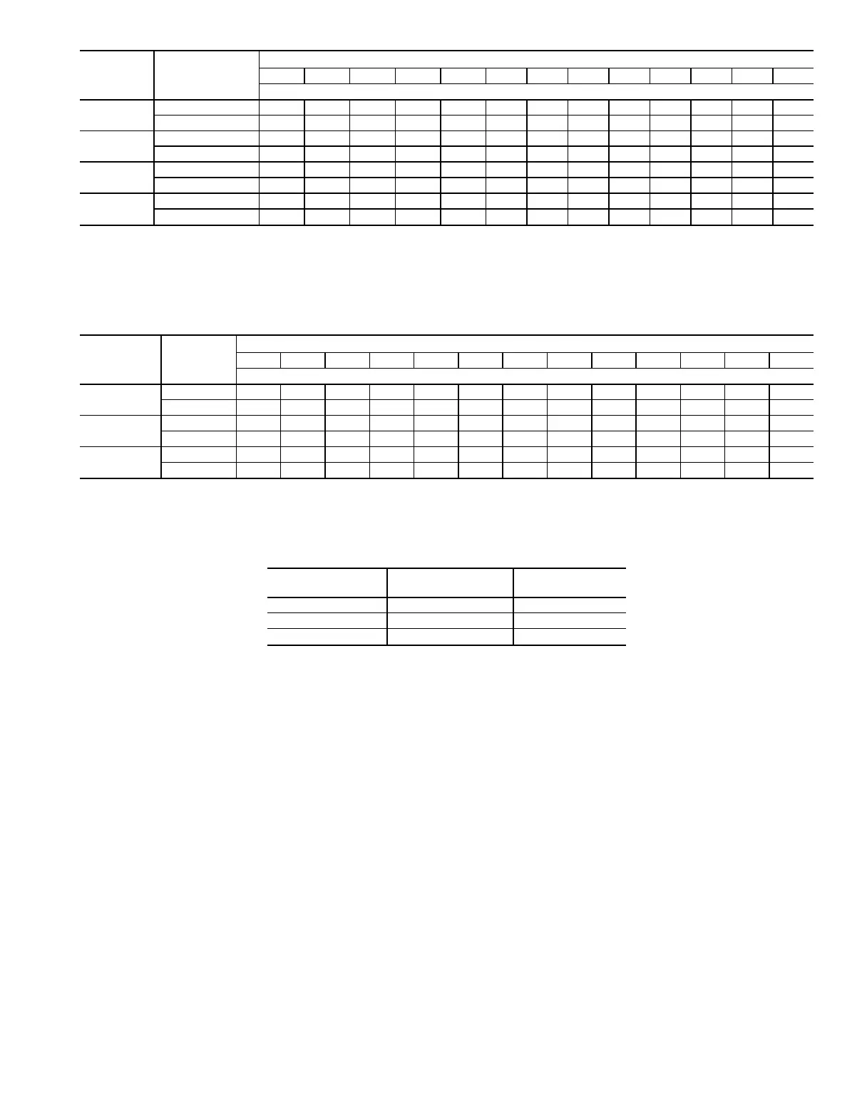
Table 6 — Steam Coil Connection Sizes
FACE
AREA
CONNECTION
39T UNIT SIZE
07 09 11 13 17 21 26 32 39 49 61 74 92
Nozzle Size (in. MPT)
LARGE
Inlet 3333333——————
Outlet 2222222——————
MEDIUM
Inlet ———————333333
Outlet ———————222222
SMALL
Inlet 2
1
⁄
2
2
1
⁄
2
2
1
⁄
2
2
1
⁄
2
2
1
⁄
2
33333333
Outlet 1
1
⁄
2
1
1
⁄
2
1
1
⁄
2
1
1
⁄
2
1
1
⁄
2
22222222
BYPASS
Inlet 2
1
⁄
2
333333333333
Outlet 1
1
⁄
2
222222222222
NOTE: The following sizes have two coils: medium face area — sizes 61-92; bypass face area — size 92.
Table 7 — Operating Charge (Approximate) — Direct Expansion coil
NUMBER
OF
ROWS
FACE
AREA
39T UNIT SIZE
07 09 11 13 17 21 26 32 39 49 61 74 92
Refrigerant R-22 (lb)
4
Large 4 5 5 6 8 11 13 14 19 21 30 38 45
Medium 34 557910111219213038
6
Large 5 7 7 9 12 15 19 25 31 39 47 53 66
Medium 4 6 7 8 10 13 15 19 24 31 39 47 53
8
Large 7 8 10 12 15 20 24 35 40 48 60 70 87
Medium 5 7 910131621303240486070
Table 8 — Coil Moisture Blowoff Limits (fpm)
FINS ALUMINUM COPPER
PER INCH FINS FINS
8 550 500
11 550 425
14 550 375
NOTES:
1. See
AHU Builder™
program for specific limitations. Data shown is for
general use in high latent conditions.
2. Coils with phenolic coated fins exhibit the same limitations as copper
fins.
3. Units apply to clean, properly maintained coils.
19