SPECIAL PIPING WITH 4 SPLITS PER COIL
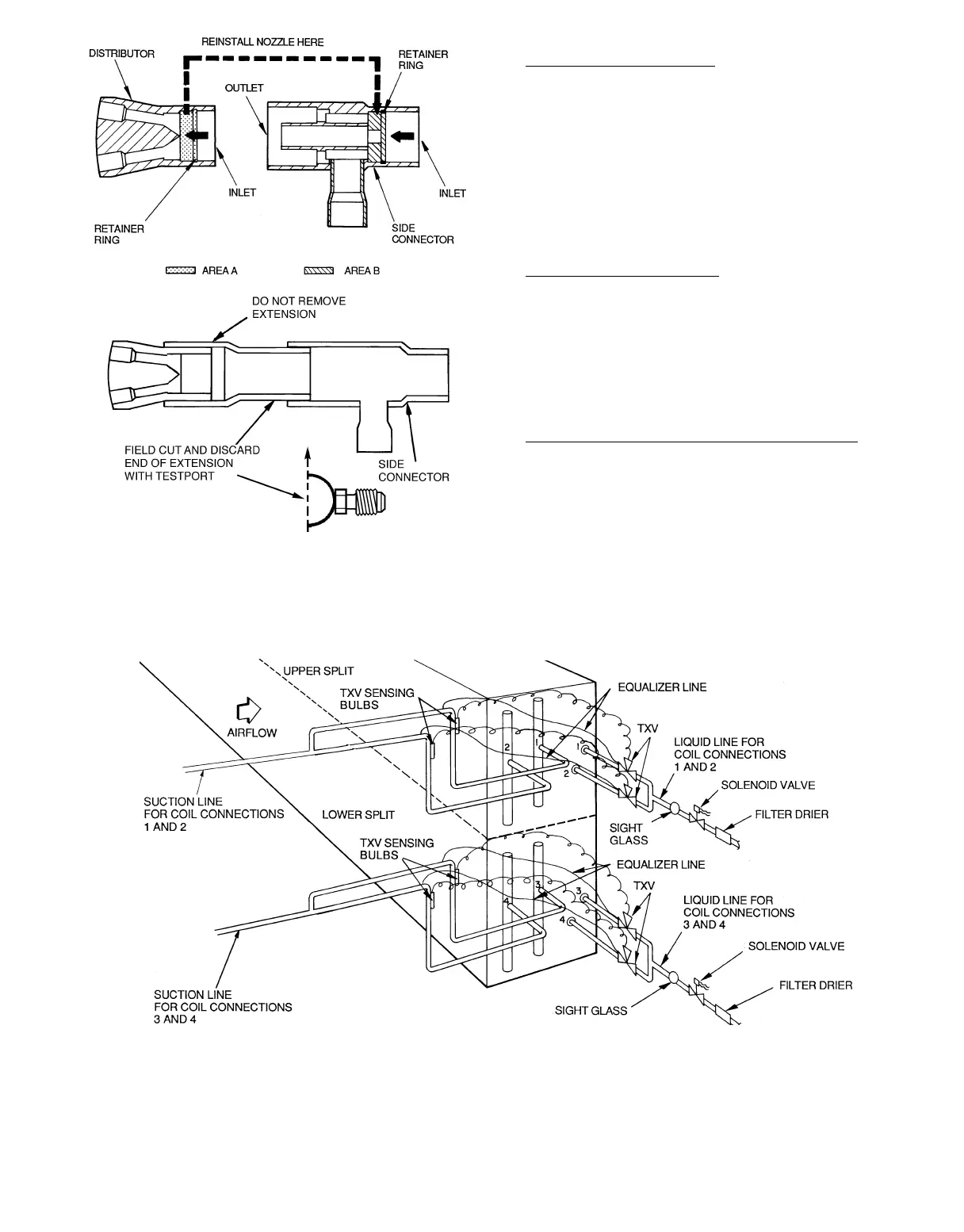
Manifolding for 2-Face Splits— Refer to Fig. 50 and exter-
nally manifold as follows:
1. Connect the 4 expansion valves to the 4 distributors on
each coil and connect the 4 suction lines to the
15-diameter-long risers as outlined in previous piping
instructions.
2. Install common liquid line for upper face split to first
(upper) and second expansion valves. Also, install a com-
mon suction line from suction lines attached to first
(upper) and second suction header connections.
3. Repeat step 2 for lower face split using third and fourth
distributor and suction connections.
Manifolding for 2-Row Splits — Refer to Fig. 51 and ex-
ternally manifold as outlined for the 2-face splits with the
following exceptions:
1. Manifold in pairs, the first and third coil connections for
one split.
2. Manifold the second and fourth pairs of coil connections
for the other split.
NOTE: Split section using first and third pairs of coil con-
nections should be first on, last off.
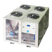
Hot Gas Bypass Connection with 4 Splits per Coil — For
either face or row splits connect a hot gas bypass auxiliary
side connector to each distributor of coil split that is first
on, last off. Refer to installation instructions for Hot Gas
Bypass.
Fig. 49 — Distributor and Hot Gas Bypass
Auxiliary Side Connector
LEGEND
TXV — Thermostatic Expansion Valve
Fig. 50 — Face-Split Coil Manifolding (Typical)
61