INSTALLATION
This section describes how to install 39T units, compo-
nents, and component parts. Units specified on a single or-
der are shipped with most components assembled in the speci-
fied airflow direction. The assembled unit is attached to a
single shipping skid (40-ft maximum length). When an up-
per component exceeds the 108-in. maximum height limit, it
is shipped out of its operating position on the unit skid or on
a separate skid. Some component parts also require assem-
bly or adjustment; see the section on each component type
for specific instructions.
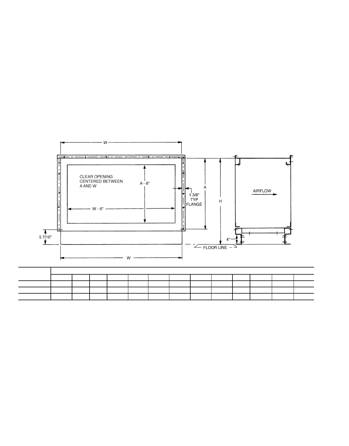
Bolting Patterns and Duct Attachment — Bolt-
ing patterns for unit and accessory flange connections are
shown in Fig. 18. Patterns for blow-thru duct attachment sur-
faces are shown in Fig. 19.
Connection Flanges — Connection flanges provide a
means of separating unit sections. The first and last com-
ponents in an assembly also have connection flanges if they
can be connected to other components. Flange separation is
described in the Pre-Installation, Rigging and Handling sec-
tion, page 22. Assemble connection flanges (shown in
Fig. 18) as follows:
1. Place the provided
1
⁄
4
-in. thick x 1
1
⁄
2
-in. wide grey foam
gasket around the perimeter of one of the flanges.
2. Rig and align the flange connections on the 2 compo-
nents so that the fastener holes are aligned.
3. Fasten the flanges together with the fasteners provided.
NOTE: Connection flanges are available on the down-
stream side of blow-thru fans (AFS5, 9 and FCS5, 9), but
NOT available on the downstream side of draw-thru fans
(AFS3, 4 and FCS 3, 4). Connection flanges are also NOT
available on the upstream side of mixing boxes (MXB1,
2, 3 and FMB1, 2).
DIMENSION
39T UNIT SIZE
07 09 11 13 17 21 26 32 39 49 61 74 92
A 2-5
15
⁄
16
2-9
7
⁄
8
2-9
7
⁄
8
3-1
13
⁄
16
3-5
3
⁄
4
3-9
11
⁄
16
4-1
5
⁄
8
4-5
9
⁄
16
4-9
1
⁄
2
5-5
3
⁄
8
6-1
1
⁄
4
6-5
3
⁄
16
7-8
7
⁄
8
H 2-10
1
⁄
4
3-2
1
⁄
4
3-2
1
⁄
4
3-6
3
⁄
16
3-10
1
⁄
8
4-6 4-9
15
⁄
16
4-9
15
⁄
16
5-1
13
⁄
16
5-9
3
⁄
4
6-5
9
⁄
16
6-9
9
⁄
16
8-1
1
⁄
4
W 4-5
11
⁄
16
4-9
5
⁄
8
5-5
1
⁄
2
6-1
3
⁄
8
6-5
1
⁄
4
6-9
1
⁄
4
7-5
1
⁄
16
7-9
1
⁄
16
8-4
7
⁄
8
9-4
3
⁄
4
104
1
⁄
2
11-8
1
⁄
4
11-8
1
⁄
4
NOTES:
1. Dimensions are ft-in.
2. Connection bolts and gasket material are factory supplied for unconnected downstream location.
Fig. 18 — Bolting Patterns — Unit and Accessory Flange Connections
34