V-Belts — When installing or replacing belts, always use
a complete set of new belts. Mixing old and new belts will
result in the premature wear or breakage of the newer belts.
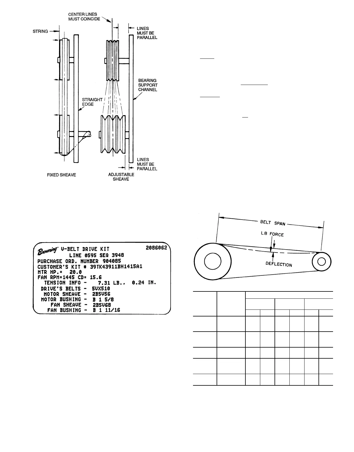
Refer to label on inside of fan access door for information
on factory-supplied drive. A typical label is shown in
Fig. 27.
1. Always adjust the motor position so that V-belts can be
installed without stretching over grooves. Forcing belts
can result in uneven stretching and a mismatched set of
belts.
2. Do not allow belt to bottom out in sheave.
3. Tighten belts by turning motor-adjusting jackscrews. Turn
each jackscrew an equal number of turns.
4. Equalize belt slack so that it is on the same side of belt
for all belts. Failure to do so may result in uneven belt
stretching.
5. Tension new drives at the maximum deflection force rec-
ommended (Fig. 28).
6. On current production, the correct tension information is
listed on the fan drive label (see Fig. 27). For older equip-
ment or for units with field-modified drives, use the de-
flection formula given in the example below and the ten-
sion data from Fig. 28.
EXAMPLE:
Given
Belt Span 16 in.
Belt Cross-Section A, Super Belt
Small Sheave PD 5 in.
(Belt Span)
Deflection =
64
Solution
a. From Fig. 29 find that deflection force for type A, su-
per belt with 5-in. small sheave PD is 4 to 5
1
⁄
2
lbs.
b. 16
Deflection =
64
=
1
⁄
4
in.
c. Increase or decrease belt tension until force required
for
1
⁄
4
-in. deflection is 5
1
⁄
2
lbs.
Check belt tension at least twice during first operating
day. Readjust as required to maintain belt tension within
the recommended range.
With correct belt tension, belts may slip and squeal mo-
mentarily on start-up. This slippage is normal and disap-
pears after unit reaches operating speed. Excessive belt ten-
sion shortens belt life and may cause bearing and shaft damage.
After run-in, set belt tension at lowest tension at which
belts will not slip during operation.
Fig. 26 — Sheave Alignment
Fig. 27 — Drive Label
BELT
CROSS
SECTION
SMALL
SHEAVE
PD RANGE
(in.)
DEFLECTION FORCE (LB)
Super Belts Notch Belts
Steel Cable
Belts
Min Max Min Max Min Max
A
3.0- 3.6 3 4
1
⁄
4
3
7
⁄
8
5
1
⁄
2
3
1
⁄
4
4
3.8- 4.8 3
1
⁄
2
54
1
⁄
2
6
1
⁄
4
3
3
⁄
4
4
3
⁄
4
5.0- 7.0 4 5
1
⁄
2
56
7
⁄
8
4
1
⁄
4
5
1
⁄
4
B
3.4- 4.2 4 5
1
⁄
2
5
3
⁄
4
84
1
⁄
2
5
1
⁄
2
4.4- 5.6 5
1
⁄
8
7
1
⁄
8
6
1
⁄
2
9
1
⁄
8
5
3
⁄
4
7
1
⁄
4
5.8- 8.6 6
3
⁄
8
8
3
⁄
4
7
3
⁄
8
10
1
⁄
8
78
3
⁄
4
C
7.0- 9.4 11
1
⁄
4
14
3
⁄
8
13
3
⁄
4
17
7
⁄
8
11
1
⁄
4
14
9.6-16.0 14
1
⁄
8
18
1
⁄
2
15
1
⁄
4
20
1
⁄
4
14
1
⁄
4
17
3
⁄
4
5V
4.4- 6.7 — — 10 15 — —
7.1-10.9 10
1
⁄
2
15
3
⁄
4
12
7
⁄
8
18
3
⁄
4
——
11.8-16.0 13 19
1
⁄
2
15 22 — —
8V
12.5-17.0 27 40
1
⁄
2
————
18.0-22.4 30 45 — — — —
PD — Pitch Diameter, inches
Fig. 28 — Fan Belt Tension Data
39