Unit Suspension — Unit suspension methods are shown
in Fig. 14. A field-supplied platform mount is recom-
mended, especially for larger unit sizes. An in-line twin-
beam mount is also recommended. Units can also be sup-
ported by attaching suspension rods to all of the lifting brackets
on all of the unit sections that have more than 15
3
⁄
4
in. of
airway length, or by suspending the unit from cross-beams
at the joint between each unit component. Ensure that sus-
pension rods are secured to adequately support the unit and
that the rods extend entirely through their associated
fasteners.
Internal Vibration Isolation — All units have inter-
nal vibration isolation and must be prepared as described in
this section before they are installed.
REMOVING HOLDDOWN BRACKETS, AIRFOIL AND
FORWARD-CURVED FANS — Remove the holddown brack-
ets (Fig. 15) as follows:
1. Open the fan access door.
2. Remove the sheet metal screws that fasten the upper hold-
down bracket to the door frame and side panels.
3. Remove the sheet metal screws that fasten the base frame
assembly to the upper holddown bracket, and discard the
bracket.
4. On the same base frame member, remove the sheet metal
screws in the base frame assembly. Remove and discard
the lower bracket and wood shipping skid.
5. Repeat Steps 1-4 on the opposite side of the fan section.
Fan sled assembly should float on isolator springs when
done.
REMOVING J-BOLT,AIRFOILAND FORWARD-CURVED
FANS (Sizes 32-92) — Remove the J-Bolt (Fig. 16) as
follows:
1. Open fan access door.
2. Locate the J-Bolt. Loosen and remove the nut securing
the J-Bolt in place.
3. Remove the J-Bolt from the unit completely by rotating
and sliding the bolt through the hole in the bottom of the
fan section.
4. Repeat Steps 1-3 on the opposite corner, and twice on the
opposite side of the fan section. Fan sled assembly should
float on isolator springs when done. A total of 4 J-Bolts
must be removed.
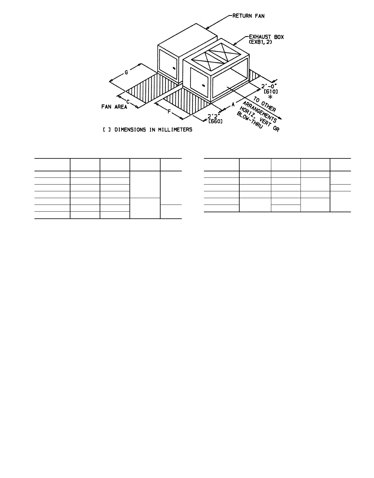
SERVICE AREA DIMENSIONS (ft-in.)
39T UNIT
SIZE
ACFG
07 4-5
11
⁄
16
2-5
15
⁄
16
2-5
15
⁄
16
2-0
09 4-9
5
⁄
8
2-9
7
⁄
8
11 5-5
1
⁄
2
2-9
7
⁄
8
13 6-1
3
⁄
8
3-1
13
⁄
16
17 6-5
1
⁄
4
3-5
3
⁄
4
2-11
7
⁄
16
21 6-9
1
⁄
4
3-9
11
⁄
16
2-2
26 7-5
1
⁄
16
4-1
5
⁄
8
39T UNIT
SIZE
ACFG
32 7-9 4-5
9
⁄
16
3-1
13
⁄
16
2-2
39 8-4
7
⁄
8
4-9
1
⁄
2
3-5
3
⁄
4
49 9-4
11
⁄
16
5-5
3
⁄
8
2-9
61 10-4
9
⁄
16
6-1
3
⁄
16
4-1
3
⁄
8
3-174
11-8
1
⁄
4
6-5
3
⁄
16
4-5
9
⁄
16
92 7-8
15
⁄
16
*Service area required for access door(s) on side opposite hand and
for coil removal.
NOTES:
1. See Table 1 for component identification.
2. Return fan and/or exhaust box is shipped separately.
Fig. 13 — Service Area Requirements, Return-Fan Unit, Sizes 07-92
31