Mixing Box Damper Actuators — The 39T mixing
boxes are supplied with low-leak dampers and blade and edge
seals. Damper operating torques are shown in Table 18.
The actuator and mounting brackets are field supplied and
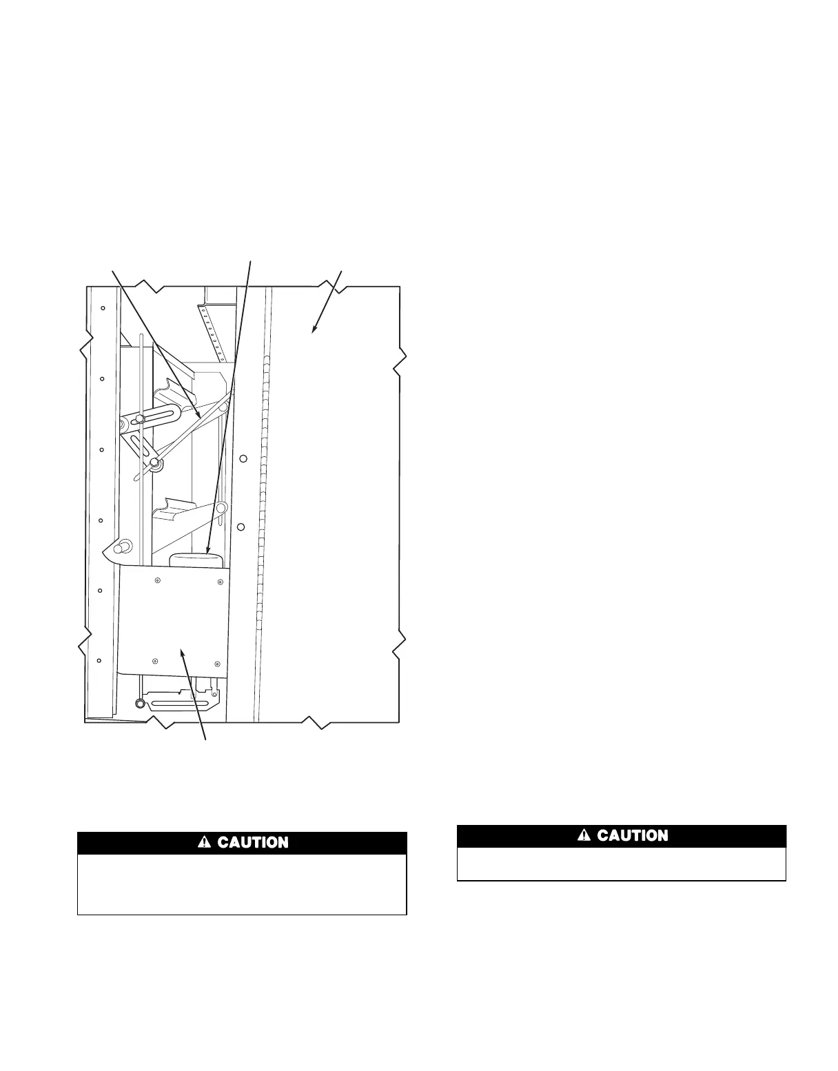
can be mounted inside or outside the unit. A typical inside
mounting bracket is shown in Fig. 35. For external mount-
ing of actuators, drill or punch a hole in the exterior panel.
To ensure torque is transmitted equally to both damper
sections, actuator must be connected to the blade shaft that
drives the interconnecting linkage bar. Connection to any other
shaft is not recommended.
On mixing box, attach actuator drive shaft to the inter-
connecting damper drive linkage plate located between the
dampers.
Mixing Box/Filter Mixing Box Damper Linkage
It is important to properly link the outdoor air and
return air dampers. Failure to do so may cause mixing
problems, stratification, or coil freezing under some con-
ditions, especially in combination type filter mixing boxes.
Refer to Fig. 36 for typical damper arrangement and con-
necting rod position. Figures 37-40 show actuator connec-
tion points and damper arrangements according to unit size
and configuration.
All factory mounted actuators ordered with the equip-
ment, have linkages preset for top outdoor air and adjusted
at the factory. If the rear dampers are to be used for outdoor
air, the actuator must be removed from the top damper and
reinstalled on the rear damper. The linkages must also be
readjusted for proper operation. Refer to the Field Supplied
and Installed Actuators section below for directions.
Top and rear dampers are shipped with both dampers in
closed position. Loosen the swivel on the interconnecting
linkage bar and fully open rear damper, leaving top damper
closed. Retighten the swivel.
FIELD SUPPLIED AND INSTALLED ACTUATORS — If
one or two actuators are used, they must be mounted to the
outdoor-air damper jackshaft. To properly set the connecting
linkages, determine the rotation required to open the outdoor-
air damper. For clockwise rotation, refer to Fig. 36 and fol-
low the procedure below. If counterclockwise rotation is re-
quired, reverse the offset dimensions.
1. With the outdoor-air damper fully closed install the
crankarm on the outdoor-air damper jackshaft at a posi-
tion which is offset 30 degrees counterclockwise from the
perpendicular axis line between the outdoor air and re-
turn air damper jackshafts.
2. Fully open the return air damper and install the crankarm
on the damper jackshaft at a position which is offset
30 degrees clockwise from the perpendicular axis line be-
tween the outdoor air and return damper jackshafts.
3. Install the connecting rod between the two crankcarms
and secure in place. The distance from the center line to
the rod in each damper must be equal.
If more than 2 actuators are used, they must be installed
in equal numbers on each jackshaft. To properly set these
dampers, determine the rotation required for each damper
and mount the actuators so that the spring feature will open
the return air damper and close the outdoor air damper. Lock
each damper actuator to the jackshaft. Remove any factory-
supplied connecting linkage between the outdoor air and return-
air dampers. Failure to do so will damage the actuators. No
additional linkages are required for these applications.
Exhaust damper boxes are shipped with dampers in the
closed position. Adjust dampers as described in the preced-
ing section.
All damper assemblies are driven at the center between 2
damper assemblies by a jackshaft. The damper actuator arm
is supplied at center on the jackshaft. For top and bottom
dampers, the boxes may require 2 actuators. Mount one ac-
tuator on each jackshaft.
All damper crankarms have 90 degrees travel from open
to closed. They may be adjusted to suit actuator location.
Damper actuators can be mounted on the bottom panels
of the unit. See Table 18 for operating torque requirements.
ZONE DAMPER LINKAGE (Fig. 22) — Note that damper
control levers and a common operating bar are factory in-
stalled on upper end of damper shafts on top of zoning damper
assembly. To facilitate the installation of field-supplied damper
operators, the operating bar may be cut and the control le-
vers repositioned as follows:
At no time should any ductwork be supported by the
unit, as damper operation may be impaired.
1. Check job prints to determine number and size of zones
required and damper operator locations.
2. Cut and remove portion of operating bar between zones
as required.
3. Install actuators on field-fabricated support brackets. Con-
nect actuator linkage to zone damper control lever.
4. Adjust actuator for correct damper operation. Be sure
actuator, linkage, and dampers operate freely. See
Table 18 for operating torque requirements.
INTERCONNECTING
LINKAGE BAR
ACTUATOR MIXING BOX
ACCESS DOOR
MOUNTING BRACKET
Fig. 35 — Typical Mixing Box Actuator Mounting,
Sizes 32-92
45