Face and Bypass Damper Linkage — All face and
bypass damper sections are shipped completely assembled
and operational. Sizes 07-11 are built as single assemblies.
Sizes 13-61 have two damper assemblies linked by a jack-
shaft. Sizes 74 and 92 have 3 damper assemblies linked by
two jackshafts.
All damper crankarms have 90 degrees of travel from open
to closed. They can be adjusted to suit the actuator location.
The face and bypass operating shaft is extended through
both sides of the unit. Actuators can be linkage connected or
direct connected. For direct conection actuators remove factory-
installed crankcarm. See Table 18 for operating torque
requirements.
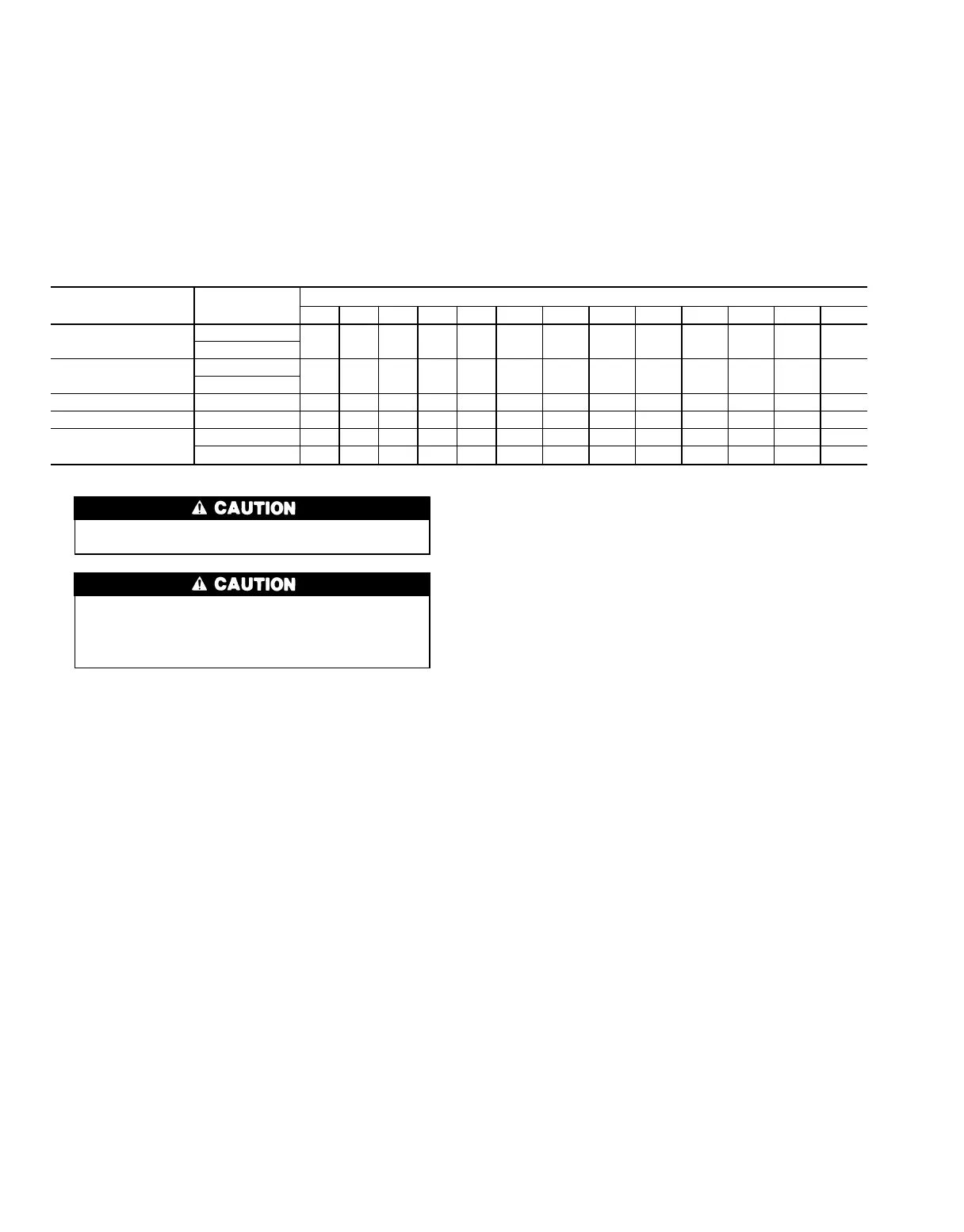
Table 18 — Damper Operating Torque (lb-in.)
DAMPER SECTION
39T UNIT SIZE
07 09 11 13 17 21 26 32 39 49 61 74 92
BOTH DAMPERS
INTERCONNECTED
MXB*
26 35 42 49 66 80 100 122 150 188 232 260 352
FMB*
EACH DAMPER
SEPARATE
MXB*
22 29 35 41 55 67 83 102 125 157 194 217 294
FMB*
EXHAUST AIR EXB* 22 29 35 41 55 67 83 102 125 157 194 217 294
FACE & BYPASS FBP 35 45 55 65 85 105 130 160 194 245 305 370 460
ZONE DAMPERS
(see Note 2)
ZDS 12 12 12 12 12 12 12 12 12 12 12 12 12
No. of Zones 55677789911121414
*Observe the following cautions:
Do not exceed 3 in. wg negative pressure in these damper
sections.
Factory duct collars and damper assemblies are for attach-
ment of ductwork only and must not be used to support the
weight of the duct. Weight bearing deflection can increase
torque necessary to operate dampers, or bind them pre-
venting any movement.
NOTES:
1. Damper shaft moves 90 degrees from open to closed position.
2. Operating torque is shown for one zone. Multiply the value shown
by the number of zones for total with one actuator.
3. See Table 1 for section identification.
44