ADJUSTING ISOLATOR SPRINGS, AIRFOIL AND
FORWARD-CURVED FANS — Units with factory-supplied
motors and drives are preset to
13
⁄
16
±
1
⁄
8
-in. clearance be-
tween the base frame assembly and the bottom panels; field
adjustment of the isolator springs is not normally required.
Units that receive field-supplied motors require isolator
spring adjustment to
13
⁄
16
-in. nominal clearance after the fan
motor, sheaves, and belts have been installed.
When adjusting fan isolation components, DO NOT en-
ter or reach into the fan cabinet while fan is running.
Serious injury can result. Be sure to disconnect power
and tag controls before making adjustments.
When field-supplied motors and drives have been in-
stalled, adjust the isolator springs as shown in Fig. 15 and 16
and described as follows:
1. Loosen the locknut.
2. Turn the adjusting stem until the specified clearance of
13
⁄
16
±
1
⁄
8
-in. is obtained. (Turn clockwise to decrease clear-
ance or counterclockwise to increase clearance.)
3. Tighten the locknut.
4. Repeat for each of the isolator springs and ensure that the
fan sled is floating on the springs.
REMOVING HOLDDOWN BOLTSANDADJUSTING ISO-
LATOR SPRINGS, PLENUM FANS — Remove holddown
bolts securing fan sled to bottom of unit. Plenum fans with
factory-supplied motors should not require vibration isola-
tor adjustment. For plenum fan with field-supplied motor,
install motor and adjust internal isolators so that fan sled is
level and does not touch bottom panels.
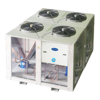
External Vibration Isolation — Install external vi-
bration isolators per certified drawings, job specifications,
and the instructions of the isolator manufacturer. See
Fig. 17.
The coil piping must also be isolated or have flexible con-
nectors to avoid coil header damage due to motion or vi-
bration. Flexible connections should also be installed at the
fan inlet (if ducted) and at the discharge.
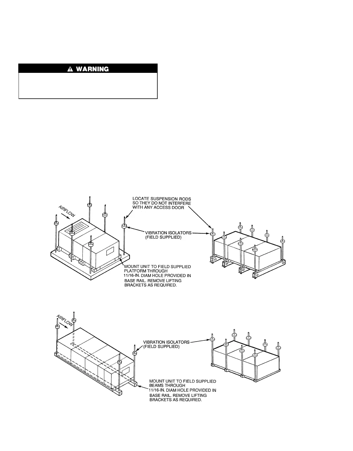
Fig. 14 — Unit Suspension
CEILING — RECOMMENDED
PLATFORM MOUNT
CEILING — ALTERNATE
CROSSBEAM MOUNT
CEILING — RECOMMENDED
IN-LINE BEAM MOUNT
CEILING — ALTERNATE
LIFTING BRACKET MOUNT
32