Condensate Drain — Install a condensate-trapping drain
line at the unit’s drain connection; use 1
1
⁄
4
-in. standard pipe.
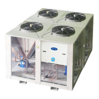
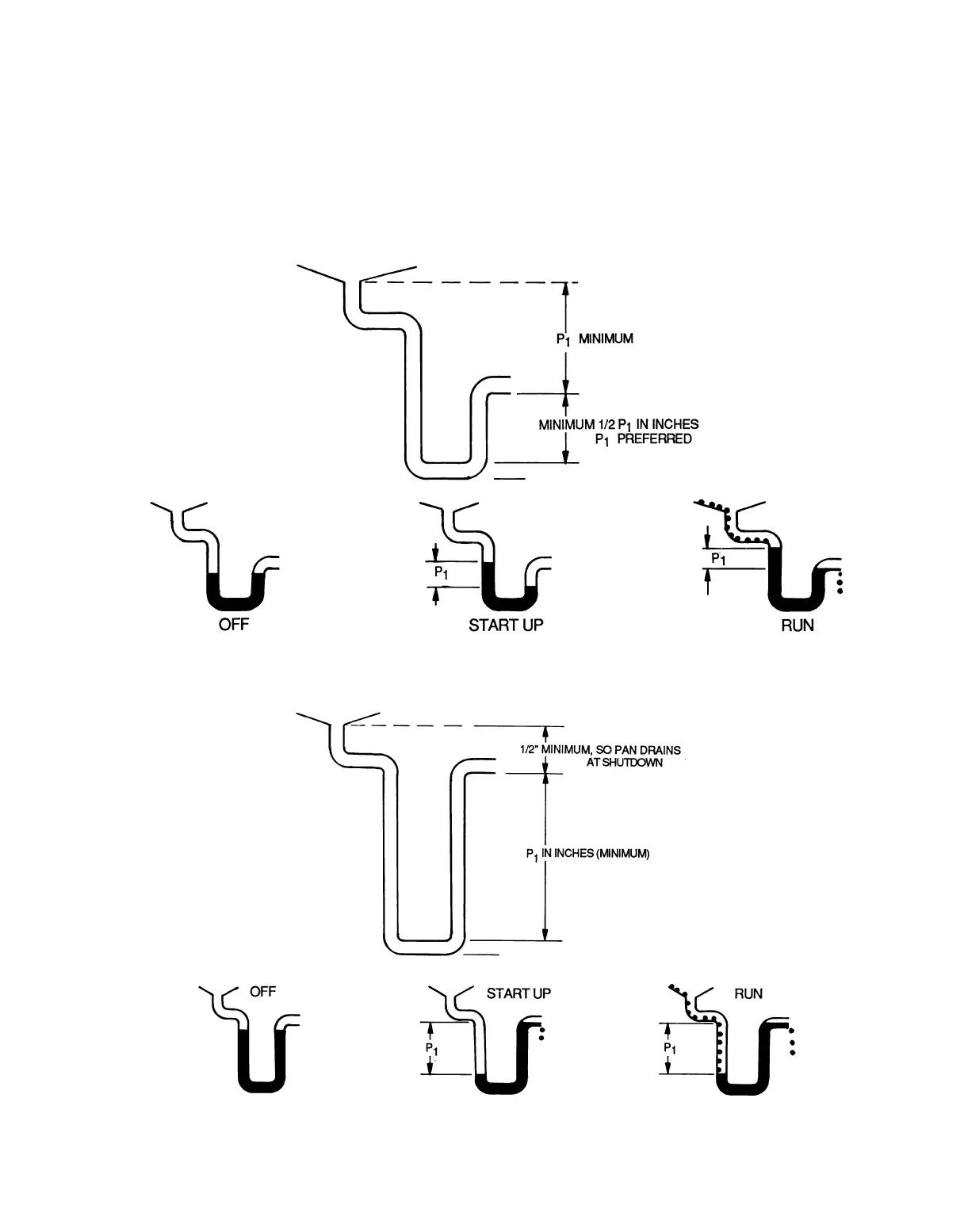
See Fig. 56 and 57 for correct drain layout.
To determine the trap dimensions for draw-thru units, cal-
culate the coil’s maximum negative static pressure (P
1
in
Fig. 56). The maximum negative static pressure equals the
pressure drop for the mixing box damper, dirty filter, and
dirty coil, at the design flow. Add 1 in. to the pressure drop.
(P
1
= negative static pressure + 1 inch.)
Traps on draw-thru units must store enough condensate to
prevent losing the drain seal at start-up. The ‘‘Minimum
1
⁄
2
P
1
’’ dimension ensures that enough condensate is stored.
To determine the trap dimensions for blow-thru units, find
the coil’s maximum positive pressure (P
1
in Fig. 57). This
figure is normally the fan total static pressure (P
1
= fan total
static pressure).
For all units, provide condensate freeze-up protection as
required. On units with internal spring isolators, be sure the
unit is mounted to allow sufficient clearance for the required
drain trap depth.
Fig. 56 — Condensate Drain, Draw-Thru Units
Fig. 57 — Condensate Drain, Blow-Thru Units
65