Field Assembled Blow-Thru Units — Both single-
and multi-zone units are built for horizontal intake and dis-
charge. Because the different discharge arrangements are con-
structed from non-interchangeable parts, they cannot be
converted in the field. Single- and multi-zone installation is
described in the following sections; see Fig. 19 and the zone
damper instructions to field-install devices in the blow-thru
discharge.
COOLING ONLY, SIZES 07-92AND HEATING/COOLING,
SIZES 07-49 — All components are completely factory as-
sembled and shipped in one piece.
HEATING/COOLING, SIZES 61-92 — Heating coils and
zone damper sections are shipped out of their normal posi-
tions on separate skids.
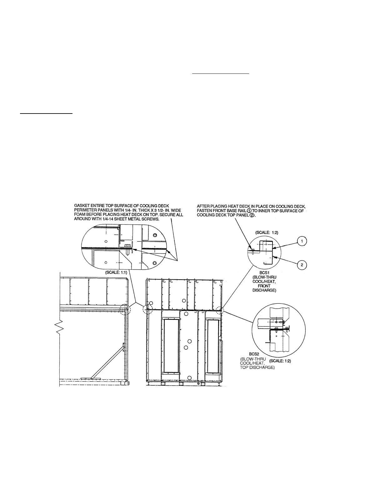
Heating Coil Section— Refer to Fig. 21 and install the sec-
tion as follows:
1. Remove the two shipping channels that connect the heat-
ing coil section to the cooling coil; remove the lag screws
connecting the heating coil section to the skid.
2. Place the supplied
1
⁄
4
-in. thick x 3
1
⁄
2
-in. wide grey foam
gasket around the top perimeter of the cooling coil deck
as shown in the detail in Fig. 21.
3. An attachment angle is located on the upstream side of
the cooling section. Keep the angle in place; it aligns the
heating section with the cooling section.
4. Rig the heating coil section and lift it into position on the
gasketed cooling coil section.
5. Fasten all 4 sides of the heating coil section to the cool-
ing coil section using the supplied
1
⁄
4
-14 x
3
⁄
4
-in. sheet
metal screws.
Zone Damper Section — Refer to Fig. 22 and install the
section as follows:
1. Remove the screws holding the zone damper section to
the heating coil section and remove the lag screws hold-
ing the damper to the shipping skid.
2. Place the supplied
1
⁄
4
-in. thick x 1
1
⁄
2
-in. wide grey foam
gasket around the perimeter of the cooling and heating
coil section discharges. Use two gasket strips on partition
panels to obtain double width.
3. Rig the zone damper section and lift it into position on
(vertical discharge) or next to (horizontal discharge) the
gasketed cooling and heating coil sections.
4. Fasten the damper section to the coil sections using the
supplied
1
⁄
4
-14 x
3
⁄
4
-in. sheet metal screws.
Fig. 21 — Installation of Heat Deck on Cooling Deck
36