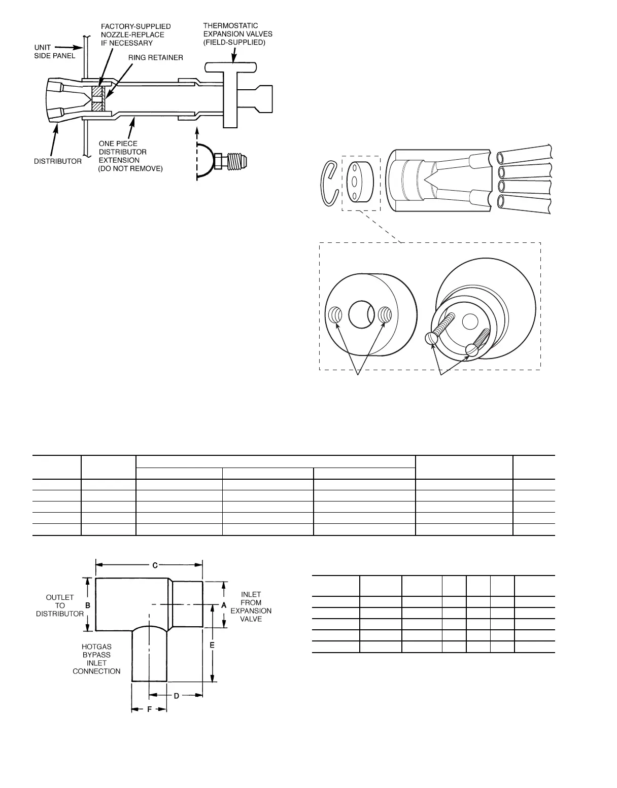
HOT GAS BYPASS — When low-load operation requires
use of hot gas bypass, hot gas must be introduced between
expansion valve and distributor.
Install auxiliary hot gas bypass side connector (field-
supplied) in coil split that is first on, last off.
NOTE: See Table 21 for auxiliary side connector sizes. Do
not attempt to use a valve that is smaller or larger than dis-
tributor size. Inserting a bushing at the outlet will defeat the
purpose of the internal nozzle tube extension.
Install the side connector as follows:
1. Remove distributor nozzle and retainer ring (area A) from
distributor and reinstall in inlet (area B) of side connec-
tor. See Fig. 49.
2. Solder field-supplied extension nipple to coupling on dis-
tributor, then to side connector outlet, using a silver
solder or equivalent with a melting point of 1300 to
1500 F. Extension nipple should be as short as possible.
3. Solder expansion valve outlet to side connector using
95-5 tin-antimony soft solder, for easy removal.
4. If required, install field-supplied adapter bushing or
coupling to connector inlet before soldering to expansion
valve outlet.
Table 21 — Auxiliary Side Connector (Hot Gas Bypass) Data
SPORLAN
TYPE
CARRIER
PART NO.
CONNECTION SIZES (in.)
USED WITH SPORLAN
DISTRIBUTOR TYPE
NOZZLE
SIZE
Inlet — ODM Solder Outlet — ODF Solder Auxiliary — ODF Solder
ASC-5-4 —
5
⁄
8
5
⁄
8
1
⁄
2
1620, 1622 J
ASC-7-4 EA19BA504
7
⁄
8
7
⁄
8
1
⁄
2
1112, 1113 G
ASC-9-5 EA19BA705 1
1
⁄
8
1
1
⁄
8
5
⁄
8
1115, 1116 E
ASC-11-7 EA19BA905 1
3
⁄
8
1
3
⁄
8
7
⁄
8
1117, 1126 C
ASC-13-9 — 1
5
⁄
8
1
5
⁄
8
1
1
⁄
8
1125, 1127, 1143 A
DIMENSIONS (in.)
SPORLAN
TYPE
ABCDEF
ASC-5-4
5
⁄
8
ODM
5
⁄
8
ODF 1.88 0.95 1.25
1
⁄
2
ODF
ASC-7-4
7
⁄
8
ODM
7
⁄
8
ODF 2.25 1.06 1.38
1
⁄
2
ODF
ASC-9-5 1
1
⁄
8
ODM 1
1
⁄
8
ODF 2.81 1.47 1.62
5
⁄
8
ODF
ASC-11-7 1
3
⁄
8
ODM 1
3
⁄
8
ODF 3.53 1.89 2.19
7
⁄
8
ODF
ASC-13-9 1
5
⁄
8
ODM 1
5
⁄
8
ODF 3.72 1.83 2.75 1
1
⁄
8
ODF
LEGEND
ODF — Outside Diameter, Female
ODM — Outside Diameter, Male
Fig. 47 — Expansion Valve Piping
RETAINER
RING
NOZZLE
BODY TUBING
SIMPLIFIED NOZZLE
REMOVAL
G
5
NO. 6-32 THREADED
PULLER HOLES
THREADED
PULLER RODS
Fig. 48 — Nozzle Change-Out
60