Mixing Box — Attach the ductwork to the mixing box
panels with sheet metal screws as shown in Fig. 23. Duct-
work should be flanged out as close to the damper frame as
possible. Do not remove the screws retaining the damper frame;
it will fall out.
Face and Bypass Dampers — Face and bypass damper
sections are shipped completely assembled with the jack-
shaft extended to the outside of the cabinet (left-hand and
right-hand). This permits mounting of the actuator to the cabi-
net exterior.
Fan Motors and Drives — When installing motors in
the field, locate the electrical junction box toward the center
of the unit. This arrangement is required for correct belt ten-
sion. Use the smallest mounting holes in the mounting base
that will accommodate the motor and provide minimum over-
hang (see Fig. 24). Tighten the motor holddown bolts.
JUNCTION BOX CONDENSATE PREVENTION — When
air handlers are installed outdoors in a high humidity envi-
ronment or indoors where the apparatus room is used as a
fresh air plenum, precautions must be taken to prevent con-
densation from forming inside the junction box of the in-
ternally mounted motor.
Standard installation practice is to mount the motor starter
or fused disconnect box adjacent to the air handler and en-
close the power wiring to the motor in flexible conduit.
The sheet metal housing of the disconnect switch or mo-
tor starter is not airtight (even when a box meeting NEMA
[National Electrical Manufacturers Association] IV stand-
ards is used). Thus, warm moist air can migrate through the
flexible conduit to the junction box on the motor. With the
motor located inside the unit, the motor temperature is that
of the cool supply air; thus, condensate can form inside the
junction box and, possibly, on the live terminal lugs.
To prevent the moist air from migrating through the con-
duit to the motor, seal the power wires inside the flexible
conduit at the motor starter or fused disconnect (Fig. 25).
Use a nonconductive, nonhardening sealant. Permagum
(manufactured by Schnee Morehead) or sealing compound,
thumb grade (manufactured by Calgon), are acceptable
materials.
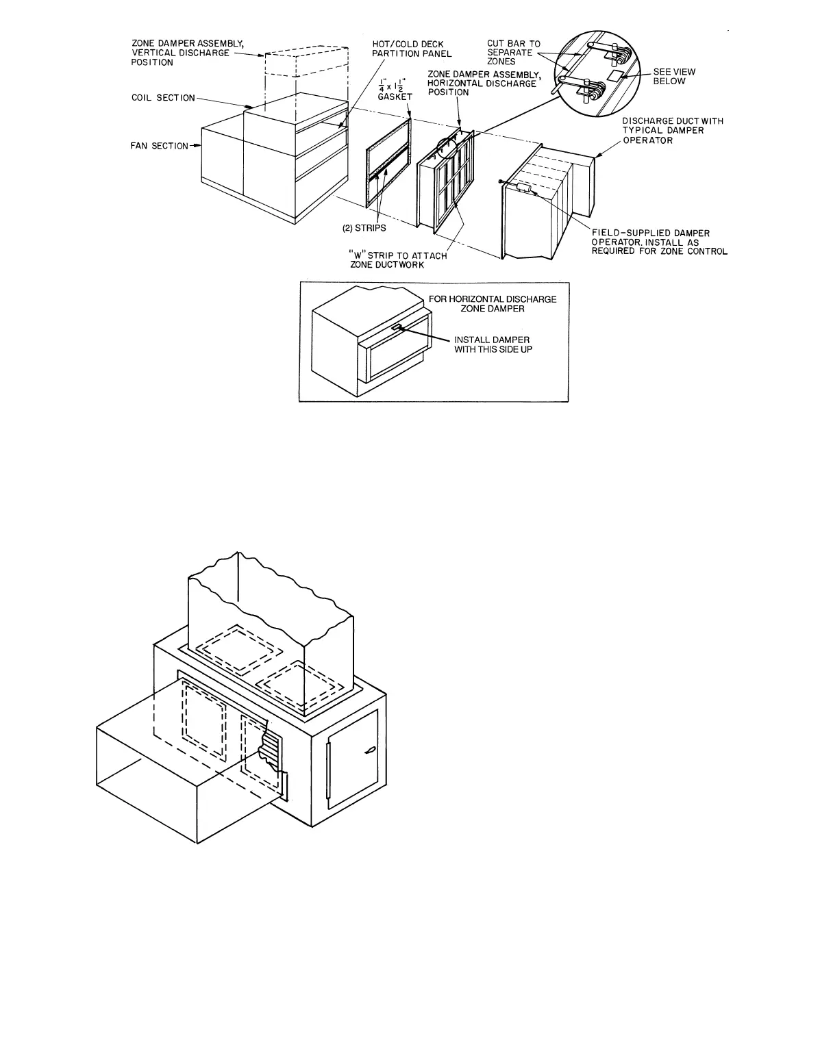
Fig. 22 — Zone Damper Assembly Details (Horizontal Discharge Shown)
Fig. 23 — Mixing Box Ductwork Attachment
37