Inlet Guide Vane Actuators, Airfoil Fans — Inlet
guide vanes are available as options on airfoil fans. They
must be adjusted in the field as follows.
POSITION ACTUATOR — The interconnecting linkage
between the two vane assemblies is factory supplied. The
actuator and mounting brackets are field-supplied. Mount
the actuator to the scroll A-frame or side plate as shown in
Fig. 32.
CHECK LINKAGE — Linkage adjustment holes are pro-
vided in the actuator crankarm; adjust the actuator and link-
age for the proper jackshaft rotation listed in Table 16. After
the linkage travel and jackshaft rotation are set, verify that
both vane assemblies move together from the fully open to
fully closed positions.
Do not force inlet guide vanes past the fully open or
fully closed positions.
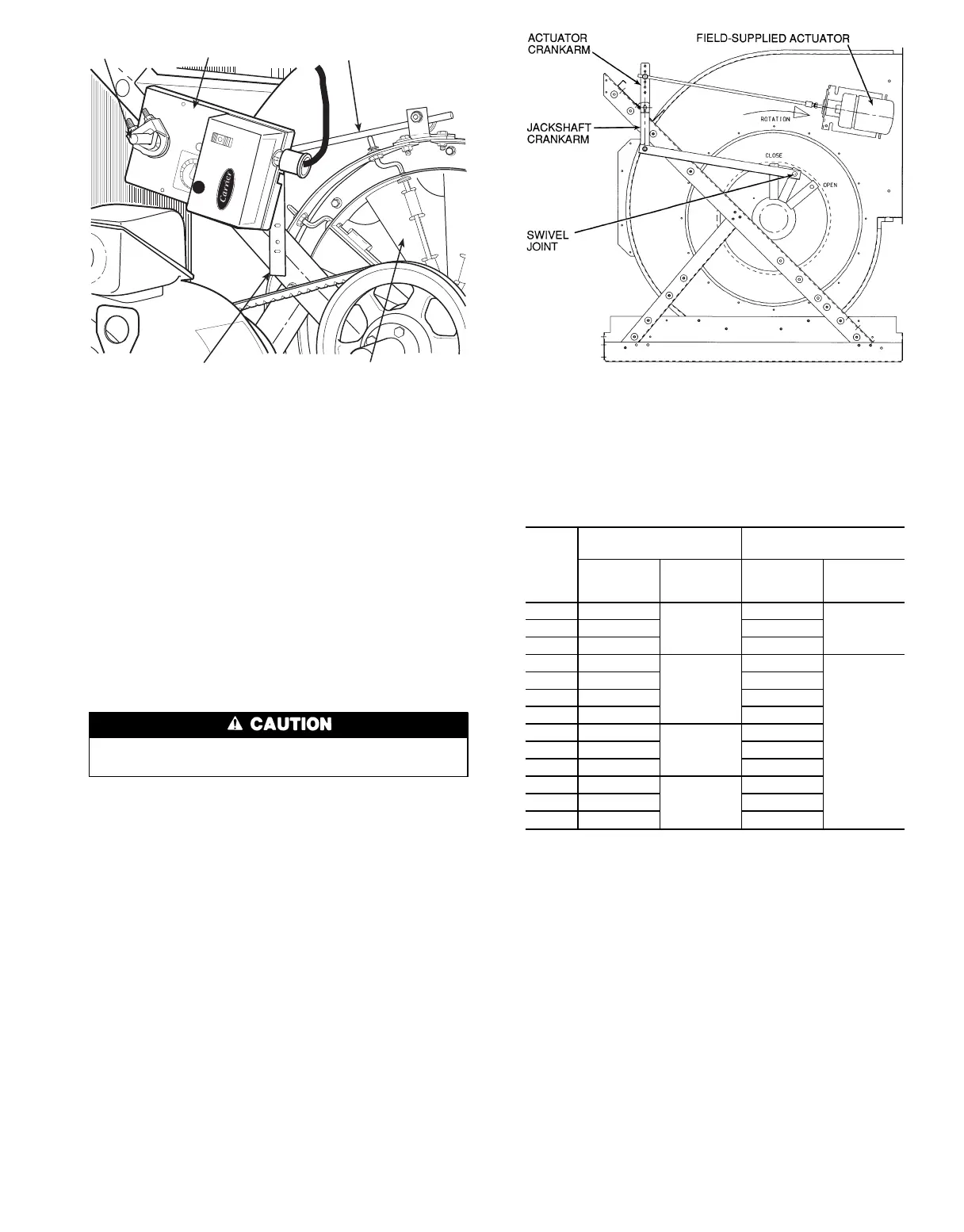
Figure 32 shows a top horizontal front discharge. With
the vanes closed, the swivel joint is at the 12 o’clock posi-
tion. With the swivel joint at the same 12 o’clock position,
other discharge arrangements (upblast or downblast) should
have fully open vanes. Regardless of the swivel joint posi-
tion, the jackshaft crankarm and swivel on the left and right
vane assemblies must be in line with each other for correct
operation.
Table 16 — Inlet Guide Vane
Actuator Requirements
39T
UNIT
SIZE
AIRFOIL FANS
FORWARD-CURVED
FANS
Jackshaft
Torque
(in.-lbs)
Jackshaft
Rotation
(Degrees)
Jackshaft
Torque
(in.-lbs)
Jackshaft
Rotation
(Degrees)
07 143
45
78
7509 182 93
11 238 93
13 195
60
104
80
17 208 150
21 310 166
26 370 185
32 359
67
185
39 435 203
49 600 222
61 487
100
265
74 579 —
92 579 —
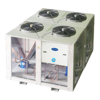
IGV
ACTUATOR
CONNECTING
ROD
ANTI-ROTATION
STRAP
INLET GUIDE
VANES (IGV)
IGV
JACKSHAFT
Fig. 31 — IGV Actuator Mounting
NOTE: When the unit is not operating, vanes may not fully close. This
condition is normal. During unit operation, airflow and pressure
differential help to control and close the vanes.
Fig. 32 — Inlet Guide Vane Linkage Adjustment —
Airfoil Fan
41