Winter Shutdown — It is recommended that auxiliary
drain piping be added to coil piping if yearly winterizing of
coils is anticipated. This auxiliary piping should be located
at the highest and lowest point on the respective header con-
nection for each coil.
ANTIFREEZE METHODS OF COIL PROTECTION
1. Close coil water supply and return valves.
2. Drain coil as follows:
Method I — ‘Break’ flange of coupling at each header
location. Separate flange or coupling connection to
facilitate coil draining.
Method II — Open both valves to auxiliary drain piping.
3. After coil is drained, Method I, connect line with a
service valve and union from upper nozzle to an anti-
freeze reservoir. Connect a self-priming reversible pump
between the low header connection and the reservoir.
Method II, make connection to auxiliary drain valves.
4. Fill reservoir with any inhibited antifreeze acceptable to
code and underwriter authority.
5. Open service valve and circulate solution for 15 minutes;
then check its strength.
6. If solution is too weak, add more antifreeze until desired
strength is reached, then circulate solution through coil
for 15 minutes or until concentration is satisfactory.
7. Remove upper line from reservoir to reversible pump. Drain
coil to reservoir and then close service valve.
8. Break union and remove reservoir and its lines.
9. Leave coil flanges or coupling open and auxiliary drain
valves open until spring.
AIR-DRYING METHOD OF COIL PROTECTION (Unit
and coil must be level for this method.)
1. Close coil water supply and return main valves.
2. Drain coil as described in procedures for Antifreeze Meth-
ods of Coil Protection, preceding.
3. Connect air supply or air blower to inlet header connec-
tion and close its drain connection.
4. Circulate air and check for air-dryness by holding mirror
in front of open vent in outlet header drain connection.
Mirror will fog if water is still present.
5. Allow coil to stand for a few minutes; repeat Step 4 until
coil is dry.
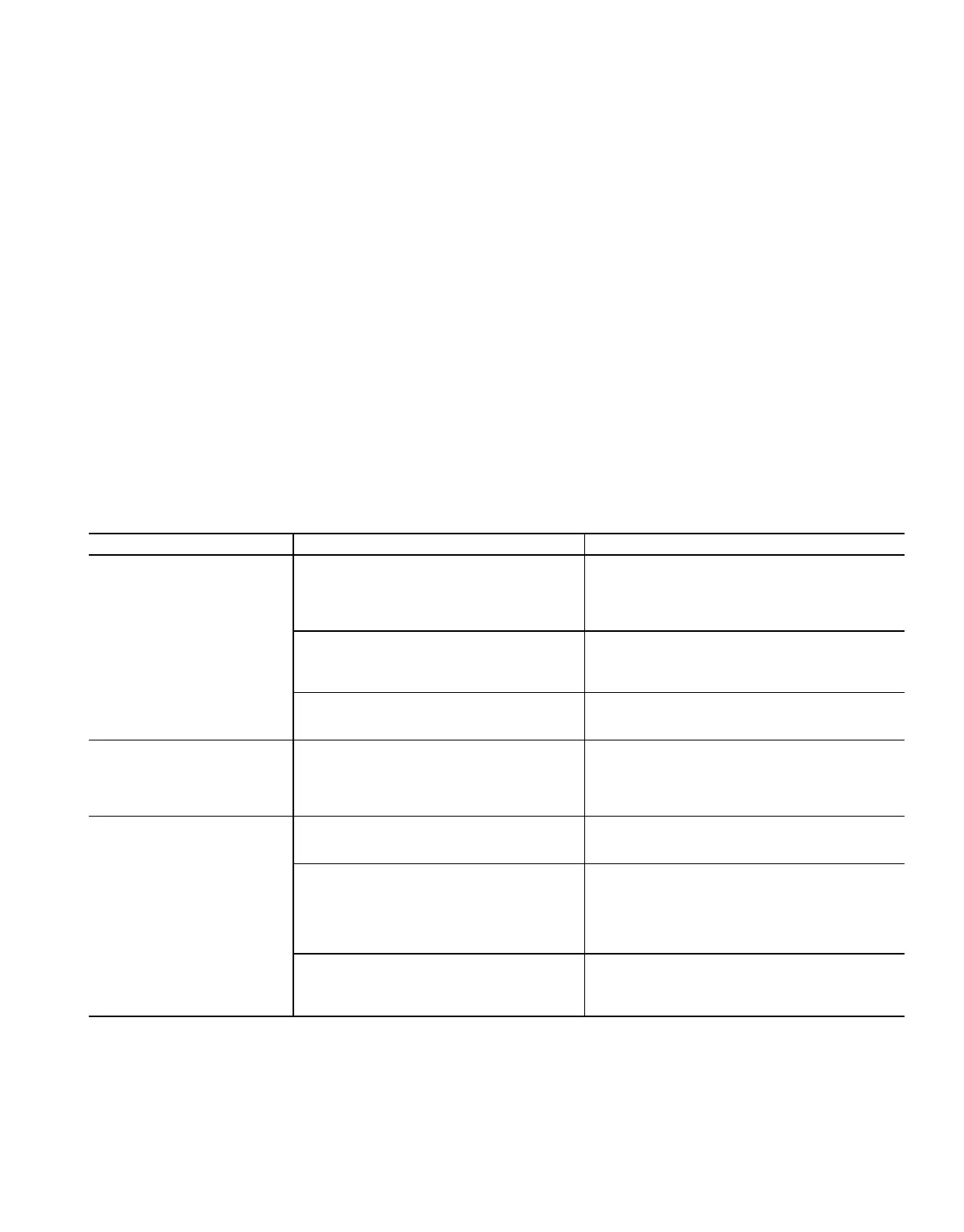
Table 24 — Electric Heater Troubleshooting Chart
SYMPTOM PROBABLE CAUSE PROBABLE REMEDY
HEATERS WILL NOT
OPERATE
Power supply failure due to faulty wiring or
incorrect fusing.
Check power supply starting at main discon-
nect switch. Check all wiring connections and
fuses.
Compare this with heater wiring diagram
(Fig. 59) and electrical data, Table 22.
Unit airflow insufficient to close airflow
switch.
Check unit fan speed per job specifications. Be
sure all ductwork, airways, grilles, and registers
are clean and clear. Refer to minimum airflow
requirements in Table 22.
Automatic (or manual) reset thermal cutout
may have opened when overheating oc-
curred from insufficient airflow.
Shut off heating power. Operate fans to allow
heater temperature to return to ambient so that
cutouts may be reset.
HEATER CYCLES Airflow marginally insufficient. Airflow switch may chatter and cycle heater
circuits on and off. Or, automatic reset may
open and close causing a similar situation. Re-
fer to minimum airflow requirements in
Table 22. Check that air system is clean.
IMPROPER TEMPERATURE
REGULATION
Intermittent power supply due to improper
installation.
Recheck installation procedure. Check contac-
tor operation and safety cutout switches. Refer
to heater wiring diagram, Fig. 59.
Erratic thermostat operation due to im-
proper location or frequent resetting.
Check thermostat installation instructions. Be
sure that location is not subjected to adverse
temperature changes such as those caused by
doors or windows opening. Check that occu-
pants are not tampering with thermostat
settings.
Air system characteristics are not in accor-
dance with job requirements.
Check that supply-air fan is delivering ad-
equate air volume and velocity. Check air sys-
tem balance. Be sure that heating coils are
operating.
75