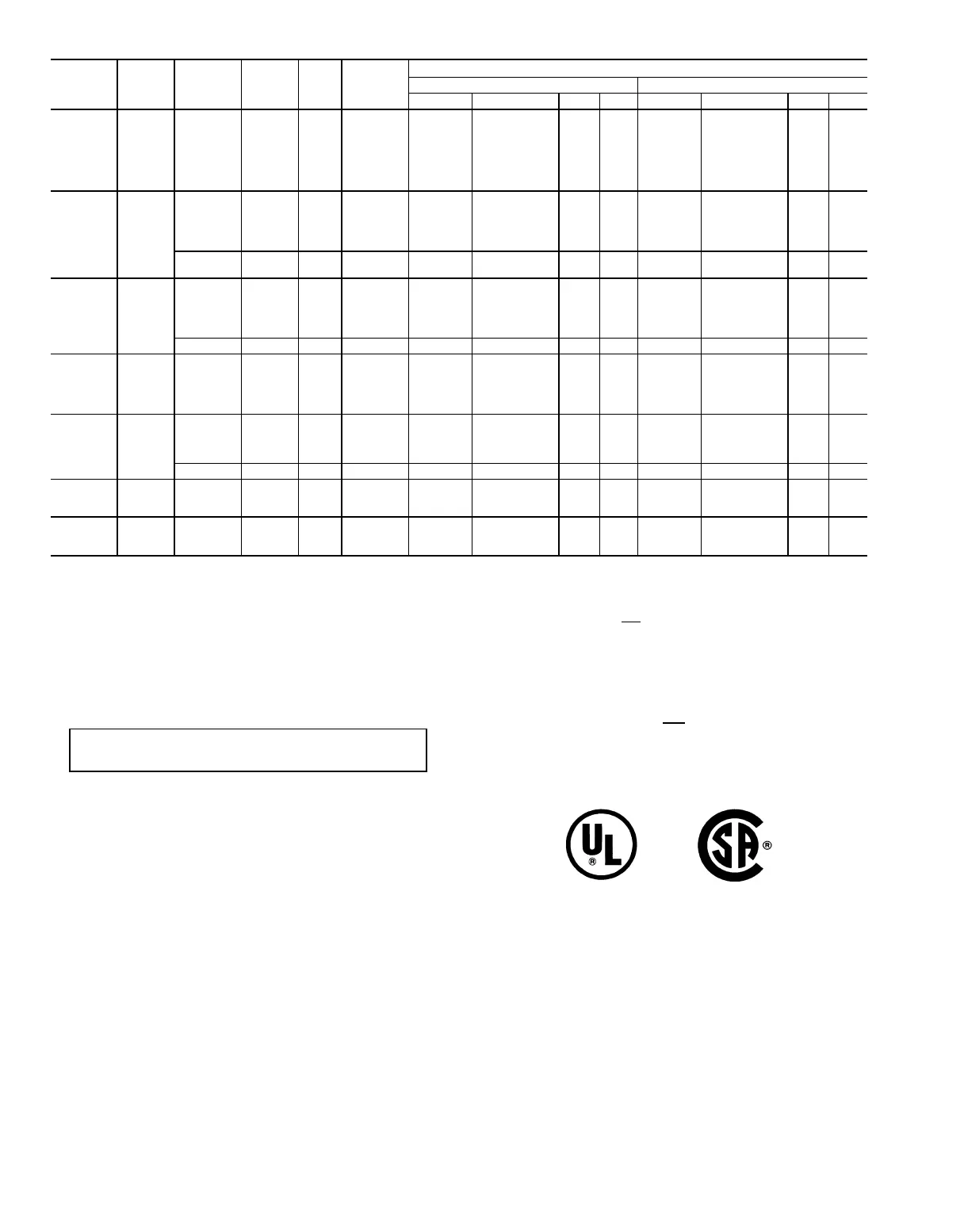
Table 22 — Electric Heater Data, Horizontal Heaters Used in EHS1
39T
UNIT SIZE
HEATER
AREA
(Sq Ft)
NO. OF
CONTROL
STEPS
HEATER
COIL
kW
TEMP
RISE
(°F)
MIN COIL
FACE VEL
(Fpm)
POWER SUPPLY, 3-PHASE CIRCUITS
208 Volts 240 Volts
Total FLA No. Sub-Ckts* MWG Fuse Total FLA No. Sub-Ckts* MWG Fuse
07 6.39 3
12 20 300 34 1 8 45 29 1 8 40
17 24 350 48 1 6 60 41 1 6 60
24 30 400 67 2 4 90 58 2 4 80
34 38 450 95 2(U) 1 125 92 2 (U) 2 110
45 45 500 125 3 2/0 175 109 3 1/0 150
57 52 550 159 4(U) 3/0 200 138 3 2/0 175
64 53 600 178 4(U) 4/0 225 154 4 (U) 3/0 200
09 8.23
3
17 22 300 48 1 6 60 41 1 6 60
24 27 350 67 2 4 90 58 2 4 80
34 33 400 95 2(U) 1 125 82 2 (U) 2 110
45 39 450 125 3 2/0 175 109 3 1/0 150
64 50 500 178 4(U) 4/0 225 154 4 (U) 3/0 200
6
78 55 550 217 5(U) 300 300 188 4 (U) 250 250
86 56 600 239 5(U) 350 300 207 5 (U) 300 300
11 9.67
3
15 17 300 42 1 6 60 37 1 6 50
25 24 350 70 2 3 90 61 2 4 80
39 32 400 109 3 1/0 150 94 2 (U) 1 125
56 41 450 156 4(U) 3/0 200 135 3 2/0 175
78 52 500 217 5(U) 300 300 188 4 (U) 250 250
6 90 54 550 250 6 400 350 217 5 (U) 300 300
13 12.77 3
29 24 300 81 2(U) 2 110 70 2 3 90
45 32 350 125 3 2/0 175 109 3 1/0 150
64 40 400 178 4(U) 4/0 225 154 4 (U) 3/0 200
78 43 450 217 5(U) 300 300 188 4 (U) 250 250
92 46 500 256 6 400 350 222 5 (U) 300 300
17 15.37
3
29 20 300 81 2(U) 2 110 70 2 3 90
45 27 350 125 3 2/0 175 109 3 1/0 150
64 33 400 178 4(U) 4/0 225 154 4 (U) 3/0 200
78 36 450 217 5(U) 300 300 188 4 (U) 250 250
6 92 38 500 256 6 400 350 222 5 (U) 300 300
21 18.62 3
45 26 300 125 3 2/0 175 109 3 1/0 150
74 36 350 206 5(U) 300 300 179 4 4/0 225
99 42 400 275 6 500 350 239 5 (U) 350 300
26 22.55 3
34 16 300 95 2(U) 1 125 82 2 (U) 2 110
74 30 350 206 5(U) 300 300 179 4 (U) 4/0 255
99 35 400 275 6 500 350 239 5 (U) 350 300
LEGEND
ARI — Air Conditioning & Refrigeration Institute
FLA — Total Full Load Amps of Electric Heating Coils
Fuse — External Fuse Size Required Per Circuit
kW — Kilowatt Rating
MWG — Minimum Wire Gage
VEL — Velocity
*(U) signifies unequal kW per step.
NOTES:
1. Subcircuits are internal heater circuits of 48 A or less ampacity.
2. Minimum wire gage is based on 75 C copper conductors; 3 conductors per
circuit.
IMPORTANT: To avoid damage from overheating, coils must not be
operated at less than minimum airflow (cfm).
Minimum Cfm = Coil Face Area x Minimum Coil Face Velocity
3. Electric heat performance is not within the scope of ARI Standard 430
certification.
4. All ratings shown are at 60 Hz. To obtain kW ratings at 50 Hz when voltage
does not change, multiply the 60 Hz rating by 0.833. For example, a 6-step
heater in a size 32 unit has a rating of 119 kW at 60 Hz. To obtain the
50 Hz rating:
119 x 0.833 = 99 kW at 50 Hz
If the voltage also varies from that shown in the table, use the formula in the
following example to arrive at the correct rating at the new voltage before
multiplying by 0.833:
Given: 2
V
2
()
kW
2
=kW
1
V
1
Where kW
1
= 60 Hz rating
kW
2
= 50 Hz rating
V
1
= 60 Hz voltage
V
2
= 50 Hz voltage
Example: 2
450
kW
2
=119
()
480
kW
2
= 105
105 x 0.833 = 87 kW at 450 v, 50 Hz
208-, 240- and 480-V 208- and 600-V
Heaters. Heaters.
68