To ensure no remaining refrigerant & air in-
side the refrigerant hoses (A, B, C, D).
Before manifold installation ensure :
Compressor Service Valves are in back seat
position
Receiver King Valve is in back seat position
Manifold gauge valves and Hoses Services
Valves closed.
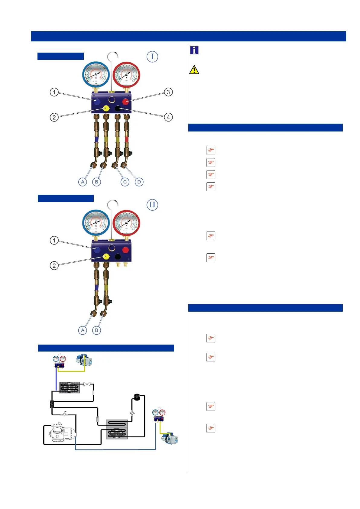
Unit connection
1. Connect the Manifold gauge (I) to the unit:
Hose (A) to LP compressor Service valve.
Hose (B) to the vacuum pump
Hose (C) to HP compressor service valve
Hose (D) to HP receiver King valve.
2. Start the vacuum pump.
3. Open the manifold gauge valves (1,2,3,4).
4. Open the hoses (B) service valve.
Vacuuming of the hoses
Wait for 1 minute.
5. Check the manifold gauges values
Must be at the lowest and stable.
6. Close the hose (B) service valve.
7. Stop the vacuum pump.
8. Disconnected the vacuum pump.
The manifold gauge (I) is installed
Evaporator connection.
1. Connect the Manifold gauge (II) to the evapo-
rator
Hose (A) to the evaporator connection
plug.
Hose (B) to the vacuum pump
2. Start the vacuum pump.
3. Open the manifold gauge valves (1,2).
4. Open the hose service valve (B).
Vacuuming of the hoses
Wait for 1 minute.
5. Check the “LP” manifold gauge value.
Must be at the lowest and stable.
6. Close the hose (B) service valve.
7. Stop the vacuum pump.
8. Disconnected the vacuum pump.
The manifold gauge (II) is installed

 Loading...


