62-61753-21
SECTION 2 -
UNIT DESCRIPTION
2.1 INTRODUCTION
LogiCOLD microprocessor equipped units
may start automatically at any time the
START/RUN-OFF switch (SROS) is not in
the OFF position. Also, the unit may be fit-
ted with two way communication equip-
ment that will allow stating of the unit from
a remote location even though the SROS is
in the off position.
Be aware of HIGH VOLTAGE supplied at
the power plug or from the generator.
When performing service or maintenance
procedures: ensure any two way commu-
nication is disabled in accordance with the
manufacturers instruction, ensure the
START/RUN-OFF switch is in the OFF posi-
tion and, whenever practical, disconnect
the high voltage source and disconnect the
negative battery connection. NEVER dis-
assemble the generator: HIGH MAGNETIC
FIELD INSIDE! This field can interfere with
cardiac implants such as pacemakers and
defibrillators.
This manual contains operating data, electrical data
and service instructions for the Vector 1550 & 1550
CITY refrigeration system.
Additional support manuals are listed in Table 2-2.
The model/serial number plate is located inside the
unit on the frame as shown in Figure 2-1.
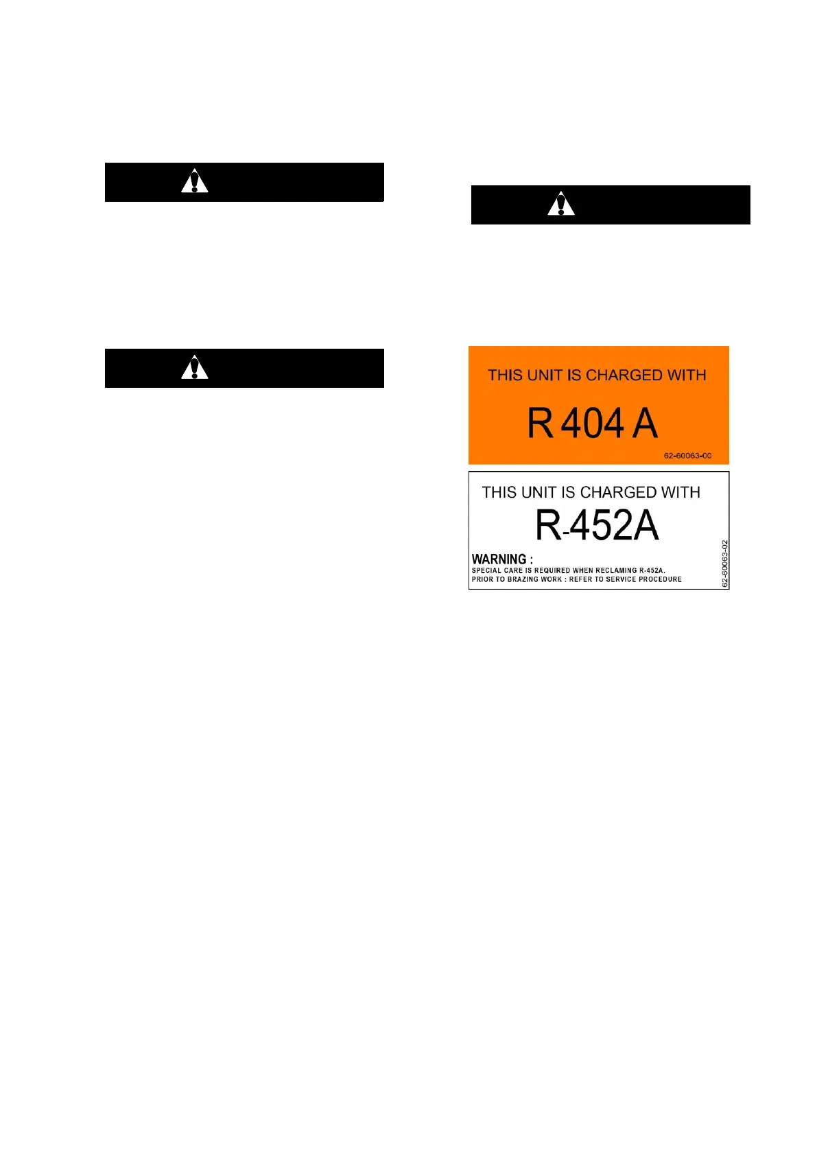
2.2 REFRIGERANT TYPES USED
The unit can be charged with R-404A or R-
452A.
Do not mix R-404A and R-452A refrigerant.
In addition to the model number, a refriger-
ant sticker informes about the refrigerant
type used by the unit.
2.3 GENERAL DESCRIPTION
The Vector 1550 & 1550 CITY unit is a hybrid die-
sel/electric, fully charged, pre-wired, refrigera-
tion/heating "nosemount" unit. The unit is used on
insulated trailers to maintain cargo temperatures within
very close limits.
Electrical power is supplied to the unit from a power
plug or by the integral generator which is driven
by the engine. The generator provides nominal
460V/3Ø/60Hz power when the engine is in high
speed and nominal 300V/3Ø/45Hz power in low
speed.
The control system is microprocessor based. Once the
microprocessor is set at the desired temperature, the
system automatically selects cooling and heating cy-
cles as necessary to maintain the desired temperature
within very close limits.
The unit can be described as having three major sec-
tions, the condensing section (Figure 2-1) which in-
cludes the engine-generator drive package (Figure
2-2), evaporator section (Figure 2-3) and controls
(Figure 2-2, Figure 2-4, Figure 2-5 & Figure 2-6).

 Loading...


