62-61753-21
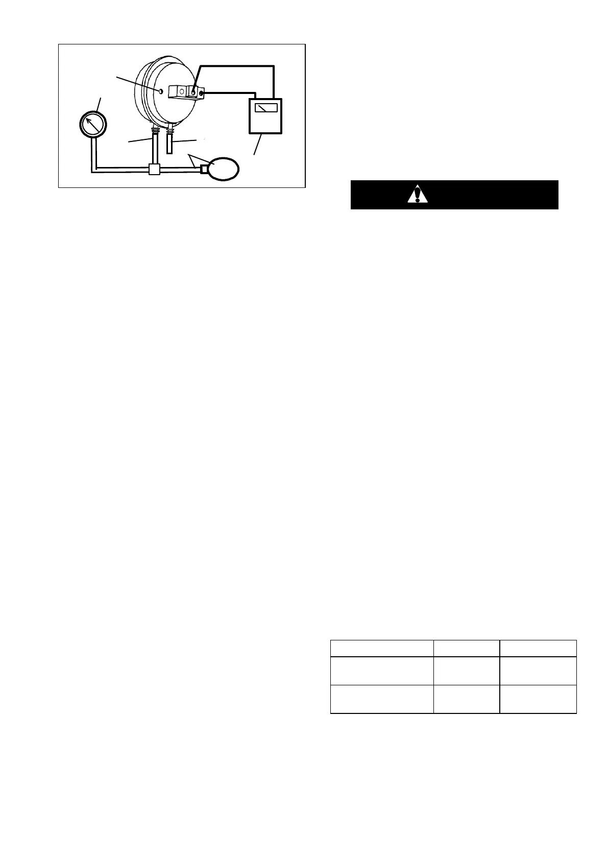
1. Ohmmeter or Continui-
ty Device
2. Adjustment Screw
(0.050” socket head
size)
3. Low Side Connection
4. Pressure Line or Aspi-
rator Bulb
(P/N 07-00177-01)
5. Magnehelic Gauge
(P/N 07-00177-00)
6. High Side Connection
Figure 8-21. Defrost Air Switch Test Setup
d. Ensure magnehelic gauge is in proper calibration.
NOTE
The magnehelic gage may be used in any po-
sition, but must be re-zeroed if position of
gauge is changed from vertical to horizontal or
vice versa. USE ONLY IN POSITION FOR
WHICH IT IS ZEROED.
e. With air switch in vertical position, connect high
pressure side of magnehelic gauge, a tee and and
aspirator to high side connection of air switch. Tee is
to be placed approximately half-way between gauge
and air switch or an improper reading may result.
(See Figure 8-20)
f. Attach an ohmmeter to the air switch electrical con-
tacts to check switch action.
NOTE
Use a hand aspirator (P/N 07-00177-01), since
blowing into tube by mouth may cause an in-
correct reading.
g. With the gauge reading at zero, apply air pressure
very slowly to the air switch. An ohmmeter will indi-
cate continuity when switch actuates. The switch
contacts should close and the ohmmeter needle
move rapidly to 0. Any hesitation in the ohmmeter
indicates a possible problem with the switch, and it
should be replaced.
h. Refer to Section 2.10 for switch settings. If switch
fails to actuate at correct gauge reading, adjust
switch by turning adjusting screw clockwise to in-
crease setting or counter-clockwise to decrease set-
ting.
i. Repeat checkout procedure until switch actuates at
correct gauge reading.
j. After switch is adjusted, place a small amount of
paint or fingernail polish on the adjusting screw so
that vibration will not change switch setting.
8.7 ELECTRICAL SYSTEM COMPONENT SER-
VICE
8.7.1 Heaters
Description
The evaporator coil heaters and drain pan heater are
energized through the power supply or engine driven
AC generator. They are used in the defrost and heat
modes.
Replacing Heaters
Be aware of HIGH VOLTAGE supplied by
the generator as the unit may start auto-
matically. Before servicing the unit, ensure
the START/RUN-OFF switch is in the OFF
position. Also disconnect the power plug
and negative battery cable. NEVER dis-
assemble the generator: HIGH MAGNETIC
FIELD INSIDE!
a. Remove the evaporator access panel.
b. Determine which heater(s) need replacing by check-
ing resistance of each heater rod (refer to section
2.11).
c. Remove hold-down clamp securing heaters to coil
or pan.
d. Lift the "U" portion of the heater (with the opposite
end down and away from coil). Move heater left (or
right) enough to clear the heater end support.
8.7.2 Evaporator Fan & Motor
The evaporator fan is of the blower type and circulates
air throughout the refrigerated compartment. The air is
drawn through the evaporator coil where it is either
heated or cooled and then discharged out the nozzles
into the compartment. The fan motor bearings are
factory lubricated and do not require additional grease.
For electrical data, refer to section 2.14.
NOTE
The evaporator blower assemblies are differ-
ent and rotate in opposite directions. Refer to
Table 8-4 for correct identification.
Table 8-4. Blower Wheel Identification
Road Side (engine
side) Blower
Curb Side (compres-
sor side) Blower

 Loading...


