62-61753-21
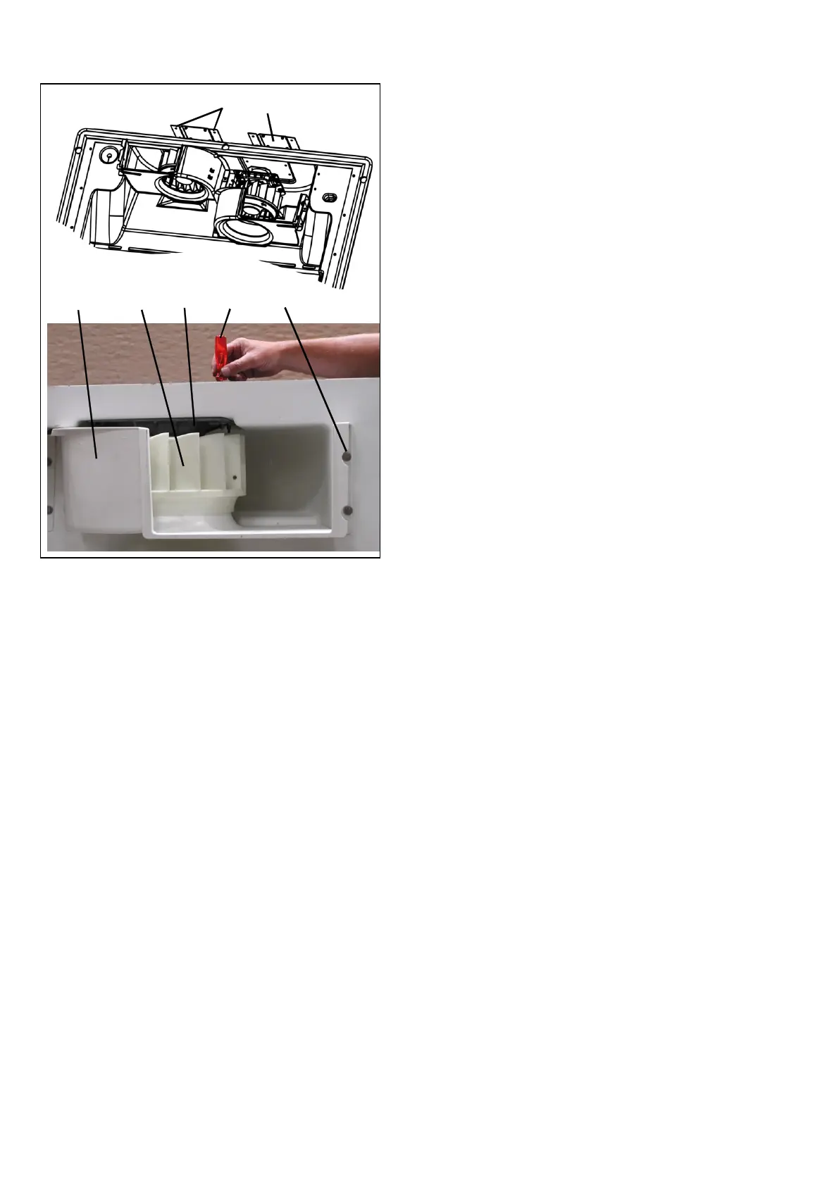
Replacing Blower Assembly
1. Screws
2. Cover plate
3. Blower housing
4. Evaporator fan
5. Motor Mount
6. Screw driver
7. Screws
Figure 8-22. Evaporator Fan Bolts
a. Working from the outside of the trailer, remove the 4
screws (item 1 Figure 8-21). Leave cover plate
(item 2) in place.
b. Working inside the trailer, remove access grill, back
panel and fan guard.
c. The evaporator blower assembly (item 4, wheel and
motor) is an integral part of the blower housing (item
3). Unscrew the 4 screws (item 7) and remove both
parts (blower assembly and housing) from the pod.
d. Remove blower assembly from housing.
e. Replace blower assembly parts as required.
f. Install blower assembly into blower housing. Install
blower assembly and housing back into the pod.
g. Working outside the trailer use a screwdriver (item
6) to align the mounting holes in the motor mount
(item 5) and cover plate.
h. Install screws (item 1). Start with two screws, re-
move screwdriver and finish assembly with the last
two screws.
i. Check that fan does not touch ring of the blower
housing.
j. Complete the assembly in reverse order of removal.
8.7.3 Condenser Fan & Motor Assemblies
The condenser fans pull air through the condenser coil
and discharge over the engine. To replace fan and
motor assembly components:
a. Open the front doors
b. Disconnect wiring. Loosen securing bolts and allow
fan and motor assembly to drop onto guide rails.
c. Slide fan and motor assembly out of unit and re-
place components as required.
d. Install the condenser fan assembly in reverse order
of removal.
8.7.4 Battery Charger(s)
Description
The battery charger (Item 2, Figure 2-2) is a solid state
device which converts the AC power, from the genera-
tor or standby power source, to 12 Vdc.
Checking Battery Charger
NOTE
The battery must be in good condition before
doing the following test.
a. Run the unit with the battery charger connected as
usual.
NOTE
If there is no load connected at the VDC out-
put, the battery charger will not deliver voltage.
b. Measure current on the +12 VDC output of the bat-
tery charger. If current is between 3 and 21 Amps
the battery charger is functioning correctly.
c. If Amps = 0 check the battery charger input AC volt-
age. It must be between 350 and 670 Volts.
d. If there is no AC voltage, stop the unit and, if re-
quired, disconnect the standby plug. Check the high
voltage 3-position connector and the 12 VDC two-
position connections.
e. If connections are good, replace battery charger.
8.7.5 Generator
Description
Driven by the diesel engine, the generator delivers AC
power to the compressor, condenser fan motors,
evaporator fan motors and the battery charger.
When the unit is in heating or defrost mode, the gen-
erator also delivers AC power to the evaporator coil
and drain pan mounted heater rods.
Preventive Maintenance & Operating Precautions
Costly repairs and down time can usually be prevented
by operating electrical equipment under conditions
which are compatible with those for which the equip-
ment was designed. Follow the instructions outlined
below to ensure maximum efficiency of the electrical
equipment.

 Loading...


