62-61753-21
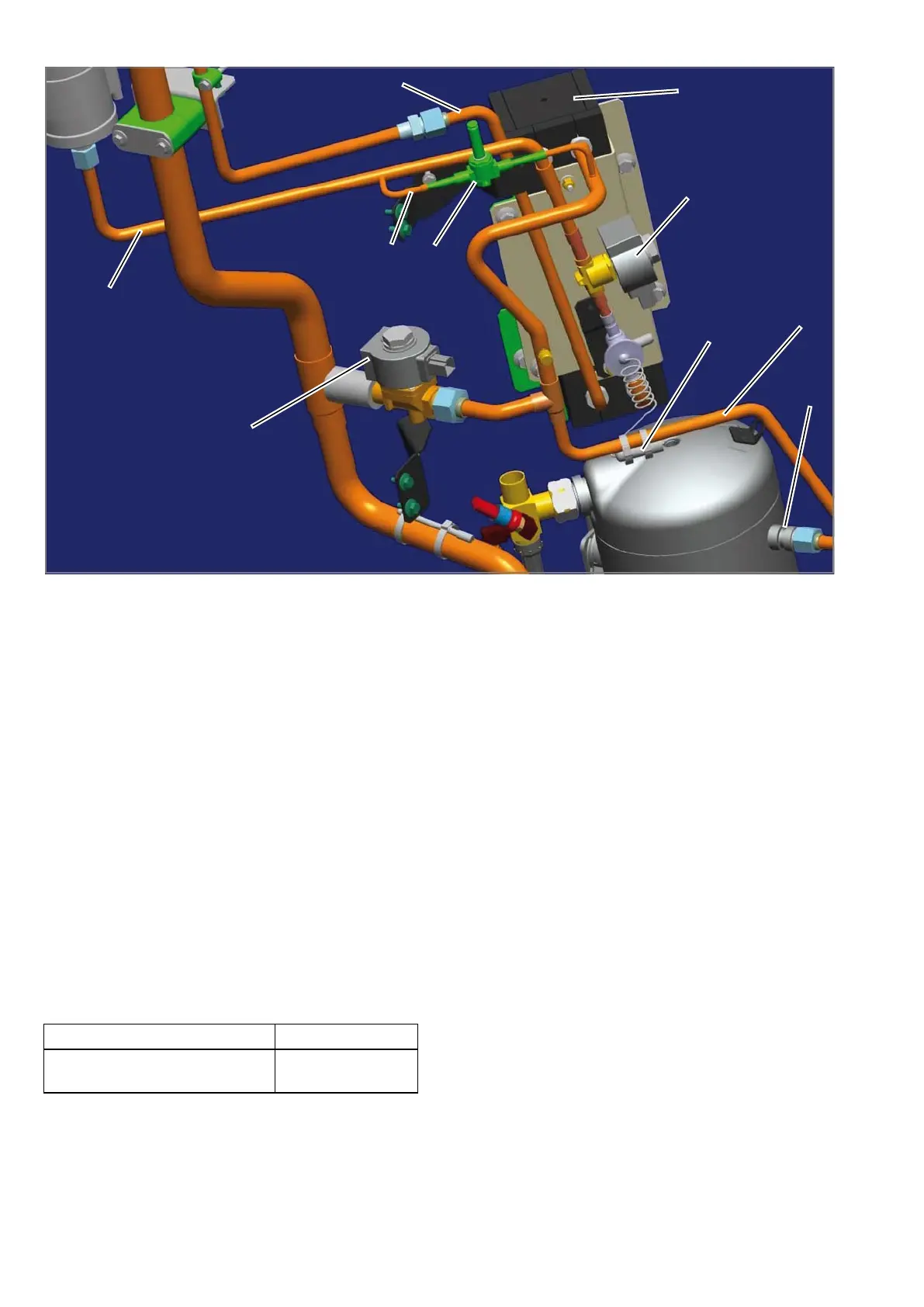
1. Liquid Inlet Line
2. Liquid Outlet Line
3. Liquid Injection Line
4. Economizer Heat Exchanger
5. Liquid Injection Solenoid Valve
6. Economizer Solenoid Valve
7. TXV bulb
8. Economizer Line
9. Compressor Economizer Connection
10. Unloader Solenoid Valve
Figure 8-13. Economizer Assembly
8.6.5 Filter Drier
To Check Filter Drier
Check for a restricted or plugged filter-drier by feeling
the liquid line inlet and outlet connections of the drier
cartridge. If the outlet side feels cooler than the inlet
side, then the filter-drier should be changed.
To Replace Filter Drier
a. Remove the refrigerant charge. (Refer to section
8.5.1).
b. Remove bracket, then replace drier.
c. Procure new O-rings. Lubricate the O-rings, back
side of sleeves and coupling nuts. Using a backup
wrench at each connection torque as follows
41 to 51 Nm
(30 to 38 ft-lbs.)
c. Leak check, evacuate the unit and charge in ac-
cordance with sections 8.5.2, 8.5.3 & 8.5.4.
8.6.6 Sight Glass Assembly
a. Remove the refrigerant charge. (Refer to section
8.5.1).
b. Remove the sight glass assembly and O-ring. Using
a new O-ring, install and torque to 50 to 60 Nm
(37-44 ft-lbs)
c. Leak check, evacuate the unit and charge in ac-
cordance with sections 8.5.2, 8.5.3 & 8.5.4.
8.6.7 Compressor Suction Modulation Valve
(CSMV)
The purpose of the SMV is to maintain the compressor
within its operating envelope and maximize unit capac-
ity and fuel economy.
At initial startup, the microprocessor will go through a
self test. When the test is complete, the Message-
Center will display "SMV CLOSING". Then the Mes-
sageCenter will display "SETTING SMV XX%" with
actual percentage depending on ambient temperature
and refrigerated compartment temperature. The unit
will then go through its normal start procedure.

 Loading...


