CHAPTER 4 - OPERATING INSTRUCTIONS
4-18
Issued 8-04 Bur 6-34551NA
CT02C236
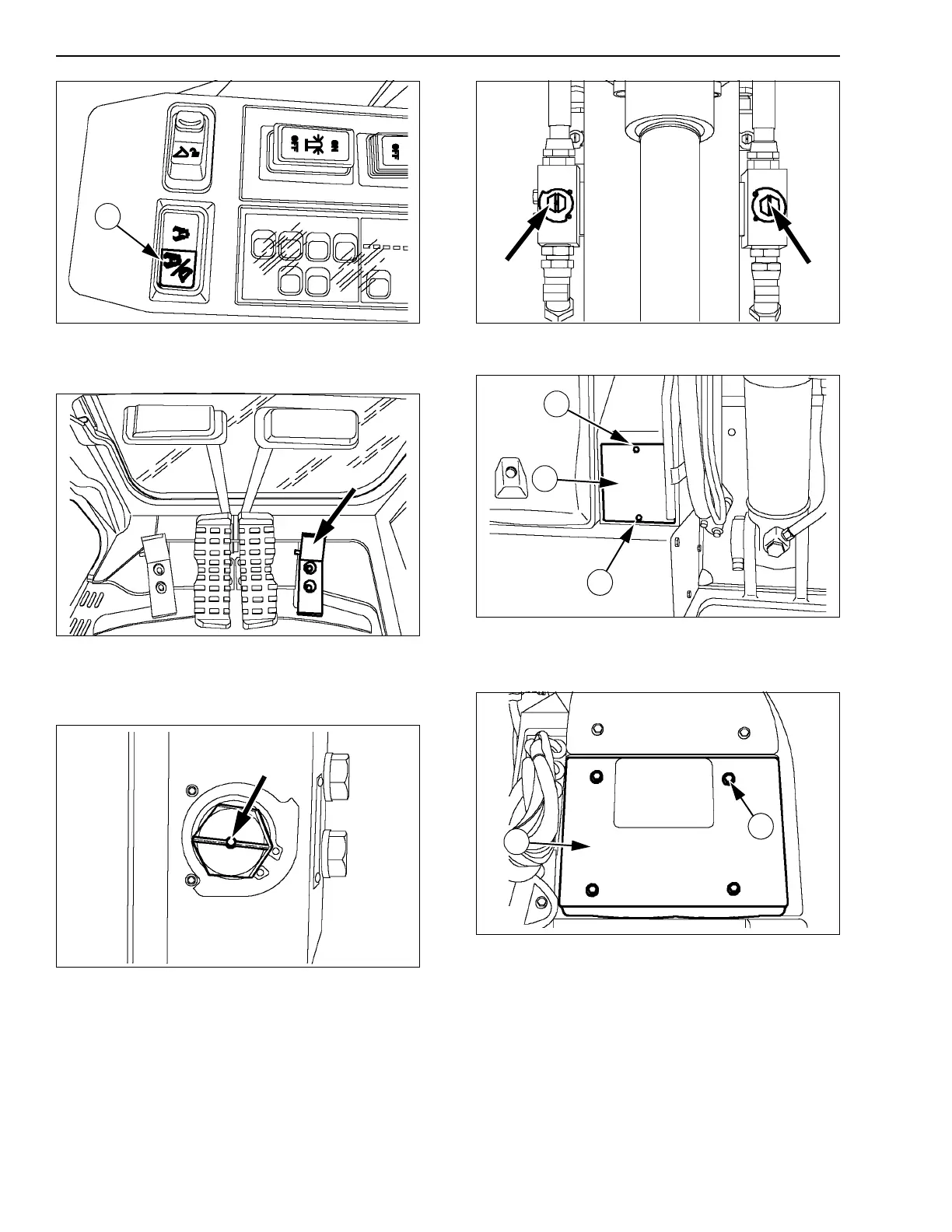
Figure 54
7. Operate the option pedal. See Option pedal in
the Controls/Instruments/Accessories section.
CT02C235
Figure 55
8. When removing the hydraulic breaker, turn the
supply valves to the closed position (-), and plug
them.
CT02C124
Figure 56
TWO FLOW DEMOLITION GRAB
CONFIGURATION
1. Proceed to connect the accessory on the supply
valves at the end of the arm.
2. Using a hex wrench, turn the supply valves 90° to
the right (I) to open them.
CT02C287
Figure 57
3. Remove the 2 screws (1) then the plate (2).
CT02C185
Figure 58
CX75SR, CX80
4. Remove the 4 screws (1) then the plate (2).
CT02C217
Figure 59
CX135SR
5. Make sure that the flow selector valve is in
position (C), if necessary, put it in position.
1
1
2
1
1
2