134
T
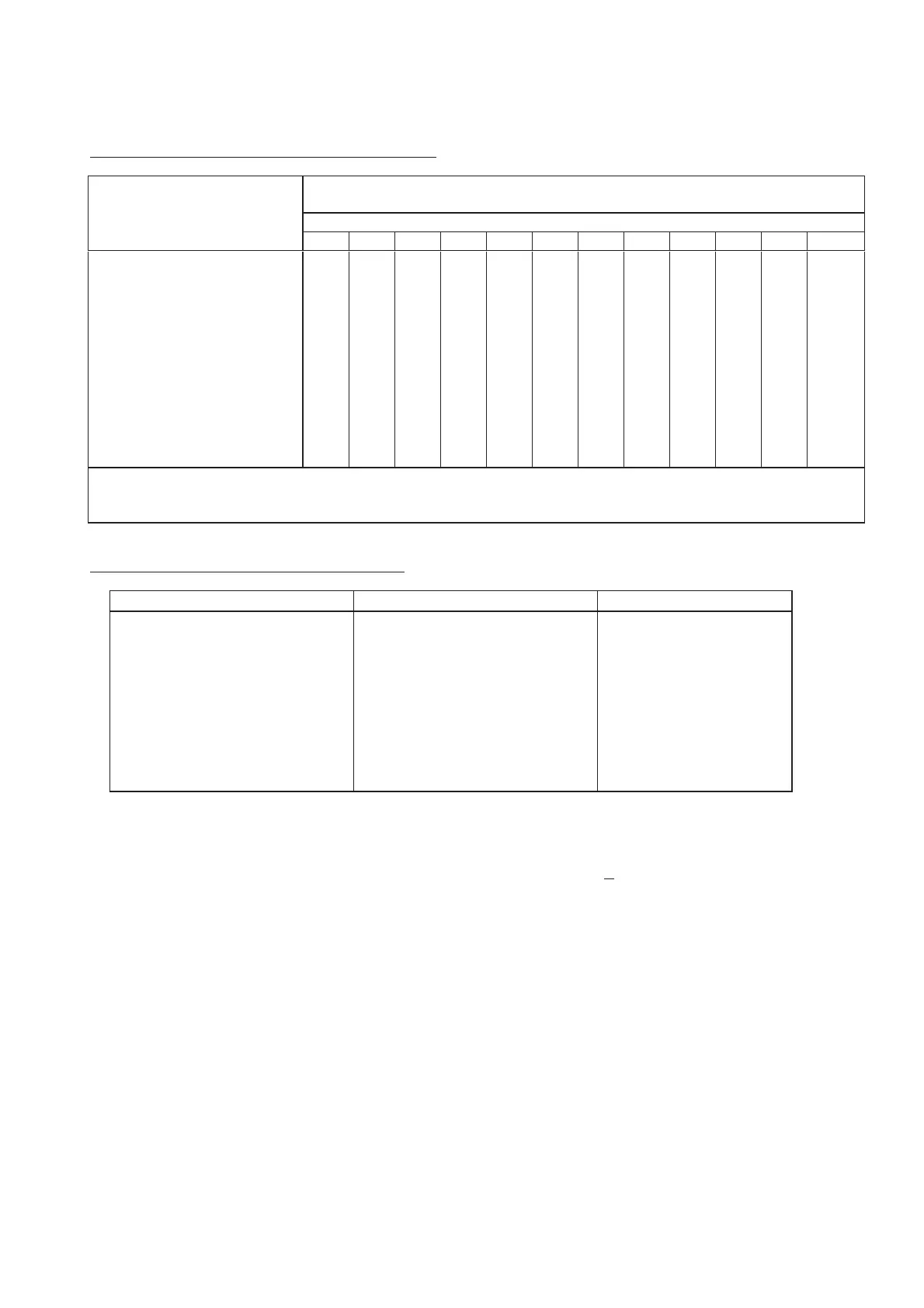
Table 38: Equivalent length of fittings and valves (G2)
Equivalent length of steel straight pipe for a C value of 120°
m
90° screwed elbow (standard)
90° welded elbow (r/d=1.5)
45° screwed elbow (standard)
Standard screwed tee or cross
(flow through branch)
Gate valve - straight way
Alarm or back pressure valve
(swinging type)
Alarm or back pressure valve
(mushroom type)
Butterfly valve
Globe valve
0,30
0,34
1,25
-
-
-
-
-
0,36
0,40
1,54
-
-
-
-
-
0,49
0,55
2,13
-
-
-
-
-
0,56
0,66
2,44
-
-
-
-
-
0,69
0,76
2,91
0,38
2,42
12,0
2,19
16,4
0,88
1,02
3,81
0,51
3,18
18,9
2,86
21,6
1,10
1,27
4,75
0,63
3,94
19,7
3,55
26,8
1,43
1,61
6,10
0,81
5,07
25
4,56
34
1,72
1,96
7,36
0,97
6,12
30,6
5,47
41,6
2,00
2,30
8,61
1,13
7,17
35
6,38
48
2,64
3,05
11,3
1,50
9,40
47,2
8,62
64,2
3,35
3,89
14,85
1,97
12,30
61,85
9,90
84,11
These equivalent lengths can be converted as necessary for pipes with other C values by multiplying by the following factors
C value 100 110 120 130 140
Factor 0,714 0,850 1,000 1,160 1,330
Table 39: Accuracy of hydraulic calculations (G3)
length
loss
of
water
application
m
m
l/min
mbar/m
mbar
m/s
m²
mm/min
0,01
0,01
1,00
1,00
1,00
-0,10
0,01
0,10
-
where
the
water
flows
join
together
at
a
junction,
the
calculation
shall
be
balanced
to
within
1mbar;
-
the
algebraic
sum
of
water
flow
at
a
junction
shall
equal
0
l/min
+
0,1
l/min.
G.2 Pre-calculated systems
G.2.1 General
G.2.1.1
Pipe
sizes
shall
be
determined
partly
from
the
following
tables
and
partly
from
hydraulic calculations.
Pipe
diameters
shall
not
increase
in
the
direction
of
flow
of
water
to
any
sprinkler.
G.2.1.2
Range
pipe
sizes
and
the
maximum
number
of
sprinklers
fed
by
each
size
of
pipe
in
the
range
shall
be
as
specified
in
Tables
G9
and
G10,
except
in
the
case
of
Light
Hazard,
where
Table
G6
specifies
only
the pipes
feeding
the
last
three
or
four
sprinklers
on
each
range.
G.2.1.3
The
size
of
all
pipes
upstream
of
each
design
point
shall
be
calculated
as
specified
in
G.2.3.2
for
Light
Hazard
and
G.2.4.2
for
Ordinary
Hazard.