CF Control 100 Electrical connection
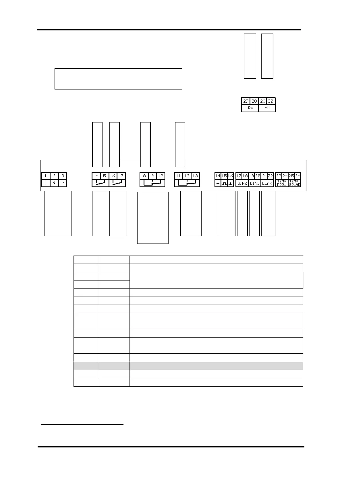
4.2 Terminals
Tab. 1
6
Power input 115V 10% or 230V 10% 50/60Hz
(Automatic switching)
from wire connector box N, L, PE
Phase from wire connector box L
Output relay 1: raise chlorine
Phase from wire connector box L
7 COM
Output relay 2: pH reduce (switchable to pH raise in
device via the menu navigation)
Output relay 3: connection 3
9 NO
Output relay 3: connection for heating pump
Phase from wire connector box L
Output relay 4: connection for filter pump
Phase from wire connector box L
6
Explanations of the table: see next page
NOTE: The terminal layout plan is
included in chapter 19 (Appendix)
These four terminals are located
in the upper right corner in the
housing.
Mains
Heating pump
or 3-way valve
Raise
chlorine
Reduce pH
Filter pump
Empty warn.
Empty warn. pH
Sample water
deficiency