Troubleshooting Edge MAXX
6-8
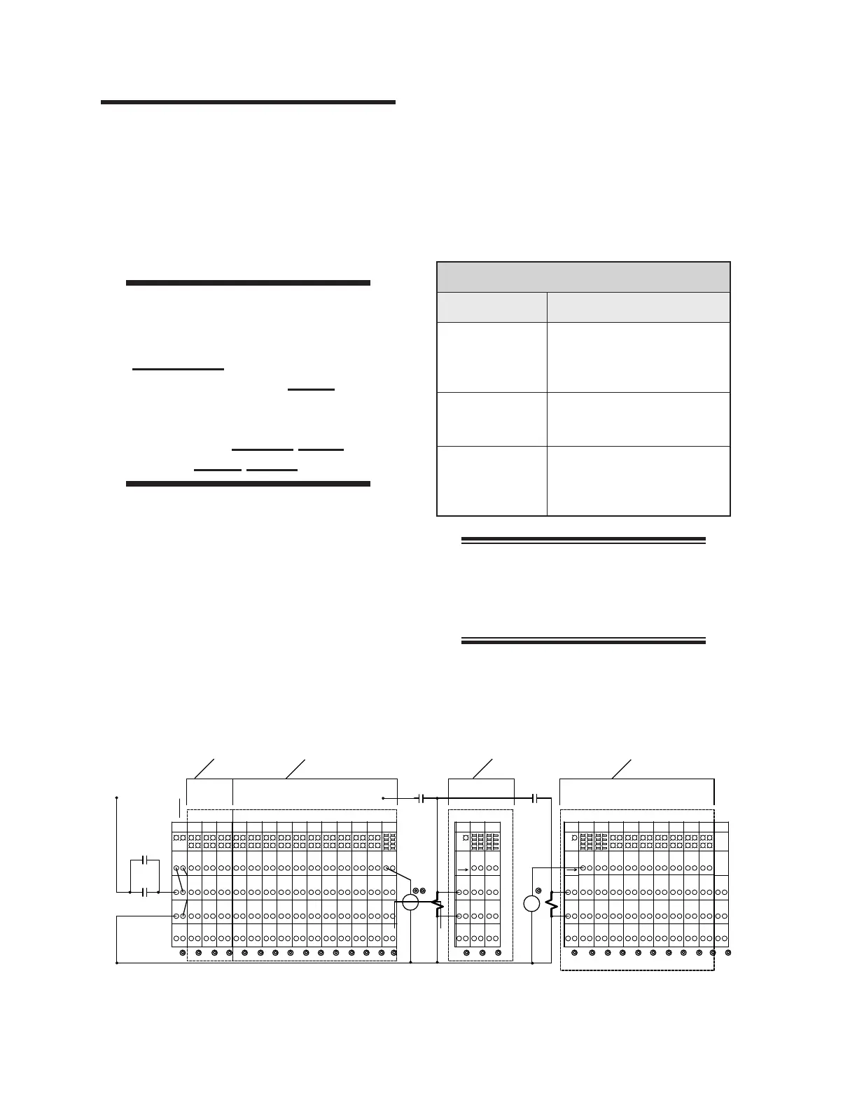
Figure 6-1: The I/O Module—electrical panel in the right end frame.
600
TERMINATOR
INPUTS
INPUTS
OUTPUTS
OUTPUTS
13
[E-STOP]
CON4A
CR1
POWER
LATCH
CONTROL
IC5
408
-24VIN
+24V
-24V
-24VIN
+24V+24V
+24V
CR1B
+24V
CC1
+24VIN
GND
-
+
0VDC
00
[CONTROL]
11 14
IC4
IC3
IC2
IC1
-24V
I17
+24VIN
I12
+24VIN
I13
I16
-24V
-
+
-24VIN
+24VIN
I20
I21
104
103
107
-24V-24V
P01
+24VIN
+24VDCI
I15
402
INTERLOCK
+24VIN
0V
24V
I10
+24VIN
I11
I14
402
-24VIN+24VIN
I18
I19
102
101
105
408402
203
204
+24V+24V+24V +24V +24V+24V +24V +24V
128
-24V
-24VIN
IC7
IC9
IC7
IC8
IC6
-24V
112
-24VIN
108
111
-24VIN
115
116
-24V -24V
-24VIN-24VIN
120
119
123
124
127
-24V
IC10
IC8
IC9
OC1
-24V
-24VIN-24VIN
131
132
-24VIN
136
135
139
-24V-24V
208
+24VOUT
140
207
206
205
A2
A1
126
408
-24VIN
408
SENSORS
110
-24VIN
106
109
113
114
-24VIN
408 408
-24VIN
118
121
117
-24VIN
125
122
408 408
-24VIN
129
130
-24VIN
137
134
133
-24VIN
408408
202
+24VOUT
138
201
530
+24VDCO
TO
POWER
RIGHT
602
P03
+24V
-24V
GND
211
219
212
220
+24V
OC3
+24VOUT
SC2
OC2
SV2
215
+24VOUT
GND
216
223
213
-24V
214
221
SC3
CR6
224
222
A2
A1
SV3
530
CLAMP CONTROL
+24VOUT
602
209
+24VOUT
RIGHT
POWER
TO
217
210
530P02
14
[RUN]
218
LATCH
RUN
CR5
11 14
236
235
227
228
-24VOUT
-24V
+24V
OC8
OC7
OC6
OC5
OC4
303
-24V
+24V
-24VOUT
+24VOUT
+24VOUT
231
232
+24VOUT
+24VOUT
239
240
+24VOUT
229
230
237
238
+24VOUT
-24VOUT
304
307
311
308
312
+24V
-24V
EC1
AOC1
OC9
OC 11
OC10
+24V
-24V
-24VOUT-24VOUT-24VOUT
315
316
319
320
323
+24V
-24V-24V
+24V
-24VOUT
324
COM
MOTION CONTROL
516
-24VOUT
301
516
-24VOUT+24VOUT
226
225
233
234
+24VOUT
530 530
-24VOUT
305
302
310
309
306
516 516
-24VOUT-24VOUT
313
314
-24VOUT
321
318
317
516516
A2
ANALOG
A1
322
0-10V
OUT
556
[START]
11
CR0B
14
6.2 LED Diagnostics
Most of the control circuits on the unit operate
in a similar way. If there is a malfunction, use
this procedure to trace each of the components
to find the problem.
Press a STOP button and open the left
end frame.
WARNING
The safety interlock switches
are only to be defeated
temporarily while performing
this procedure. Never
operate the unit unless all
safety systems are working
correctly. Serious Injury
Could Result.
The unit will not operate while a safety
interlock switch is open. As a temporary
measure during this work, defeat the in-
terlock switch.
1.
2.
To diagnose the problem, start the unit,
feed a piece and observe the problem area.
Use the CHI panel’s TEST procedures,
which are found in the CHI PANEL OP-
ERATION BULLETIN.
If a component doesn’t work, check the cor-
responding LED against the chart below:
I/O Module
LED Condition CHECK
Inputs - OFF
Device is properly aligned
and functional
Input module connection
•
•
Inputs - ON
Outputs - OFF
Module connections
Module is defective
•
•
Inputs - ON
Outputs - ON
Open circuit between output
module and device
Device is defective
•
•
NOTE: The relays have devices
dependent on them. Check for an
open circuit or a bad motor, clutch,
or contacts.
3.
4.
 Loading...